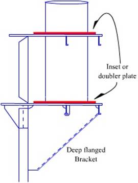
| Load Lines | Rudder & Propeller |
Ship Construction
Fittings
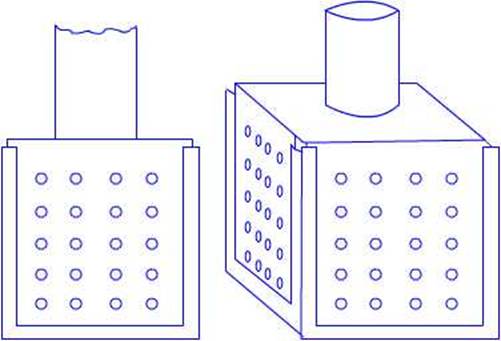
Mechanical Hatch covers
The figures shown below illustrate the various parts
of a mechanical hatch cover. These hatch covers may be made up of several
individual pontoons (so named because prior to the ‘MacGregor’
type of rolling hatch covers the pontoons had to be individually lifted and
battened down).
The
pontoons (individual parts of the hatch covers) are connected to one another
and can easily and quickly be rolled into or out of position leaving clear
hatchways and decks. The normal practice for the lengthwise opening of hatches
but sideways opening hatchways are found on large bulk carriers and OBO’s.
The smaller versions are mainly
operated either manually (using wire and winch) or electrically. The larger
ones are nearly all operated hydraulically.
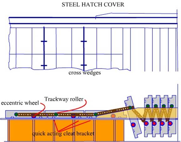
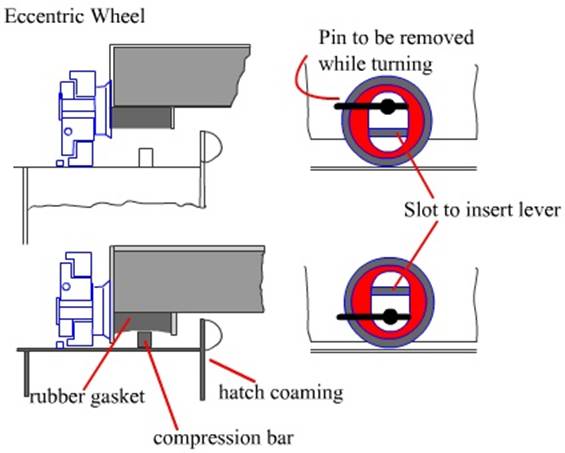
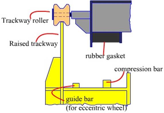
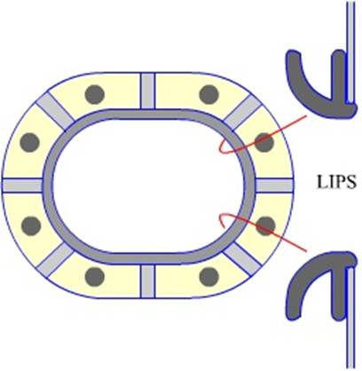
The wheels on the side on which the pontoons rollere
are eccentric in their construction thus when in the battened (lowered)
position the clearance between the wheel and the trackway
is minimum and the pontoon sits on the trackway, the
rubber gaskets being compressed by the compression bar.
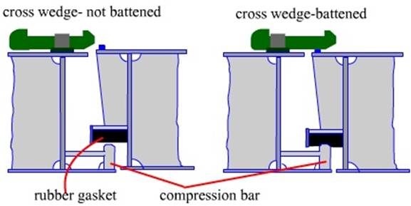
The cross
wedges are used to ensure the pontoon rubber gaskets compress against the
compression bars of the forward pontoons.
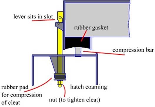
The side
cleats ensure that the pontoons stay compressed to the trackway
compression bar and the ship motion is effectively compensated or removed.
These hatch cover systems consist of various parts:
The pontoons, eccentric wheels, trackway
wheels, cross wedges, and the side cleats.
Battening down a hatch is to be done after reading the
operations manual.
A hatch cover should not be battened with cargo on
top.
The Channels are to be swept prior battening so that
the packing do not rest on dirt.
The drain channel on the front of the hatch pontoons
are to be cleaned prior closing the hatch.
Once the wheels are turned the next item to be engaged
are the cross wedges and the side cleats are to be fitted last.
Prior proceeding to sea (long voyage) the hatch cover
sealing should be tested with chalk marks made on all the compression bars – on
the hatch coaming as well as on the pontoons. The hatch is to be battened and
then opened to see if all the rubber gaskets have got chalk mark on them or not
– if not hen rectification to be done.
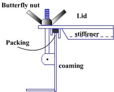
Oil tight hatchcover
These hatch covers are small in size and may have
butterfly nut locking arrangement. The sealing is done by Hi-nitrile rubber
which is not affected by oil.
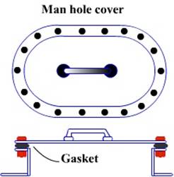
Manhole covers do
not vary much in design, their shape however are sometimes different for
different places.
When fitted outside a tank they may be either circular or elliptical. But when fitted inside they are almost always elliptical to facilitate their removal.
Usual size openings vary between 450mm to about 600mm.
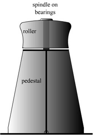
Roller, Multi‑angle, Pedestal and
A roller is to be found on the forward and after
stations area – generally at the leads to the mooring ropes as well as on top
of ‘old man’ pedestals.
These facilitate the hauling of ropes since they
reduce the friction when the rope is hauled through a panama fairlead which has
no rollers.
A panama fairlead
is o named since they were mostly used in the
A multi angle
fairlead again is a fairlead used due necessity when in the great Lakes. The
ship moves through numerous locks as the ship is made to climb a great height –
the
Mooring
bitts are prefabricated and then are welded onto the deck. The size of the bitts are dependent on their use. Thus a small
set may be fitted next to an occasional winch while the larger ones are fitted
at the mooring stations.
The bitts are hollow and as such require care to
ensure that the sides do not corroded and holed.

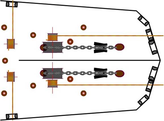
A typical
forecastle mooring and anchoring arrangement, showing the leads of moorings
Securing
anchors and making spurling pipes watertight in preparation for a sea passage
Once the anchor has been washed the anchor is hove
right up into the hawse pipe, the bow stopper is lowered and the locking pin
inserted.
The winch is reversed a little to make the chain sit
properly into the slot of the bow stopper and then the brake is tightened and
the windlass gear removed.
The anchor chain at the deck level (hawse pipe) is
lashed with extra lashings as provided by the shipyard, if none are present or
if expecting heavy weather, then extra wire rope lashings are taken, The wire
rope to be used should be tested one, if an old (good condition) life boat
falls are available then this makes a very good extra lashing wire. This wire
is flexible and can be used by hand. A number of turns (figure of eight) are
taken around two sets of bitts. The free ends being fastened by bull dog clips
at least two fixed in opposite directions.
Generally the shipyard would have provide
lashing point as well as short length of wire attached to a bottle screw. These
should be well oiled and are the most efficient for lashing the anchor. The
wire should be tight.
Once the anchor is lashed the hawse pipe covers are
not placed but stowed under deck or in their stowage positions.
The spurling pipe area is chipped to remove any
residual remains of earlier cement.
The metal spurling pipe covers are placed around the
chain and over the spurling pile. The clips provided at the edges of the covers
should be hooked to the lips of the spurling pipe.
A new canvas cover is then placed over the metal
covers just fitted and is tied around the lips of the spurling pipe as well as
the chain. No empty spaces should be found.
Cement mixture is prepared and the entire cover is
covered with this mixture.
Cable stopper
A chain stopper as shown below may be of various
designs, but all serve the same purpose – to hold the cable.
The cable is passed through the stopper – with the
holding bar lifted up – by the counterweight on top. There is a pin to hold the
bar in this
position.
Once the decision has been taken to hold the cable,
the safety locking pin is removed and the bar is eased down on top of the
cable. Note that the default position of the holding bar is to arrest the
cable, only a effort is required to keep it up.
Once the bar is placed over the cable the cable may
have to be adjusted a little to ensure that the flat part of the cable falls in
the holding area and not the vertical section, the safety locking pin is now
introduced to prevent the bar from jumping u[ in case the cable slip from the
brake.
Once the lacking pin is in position the brake can be
released and the stopper would do the work of holding the cable.

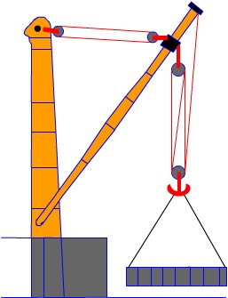
Masts and
Sampson posts
Bilge and ballast piping system of a cargo ship
The following shows a bilge and ballast line diagram
of a general cargo ship.
The bilges are all fitted with non return valves so
that not water may be inadvertently be pumped into the holds.
The bilges are serviced by a bilge pump which
incorporates a strainer and this should be checked before starting the pump.
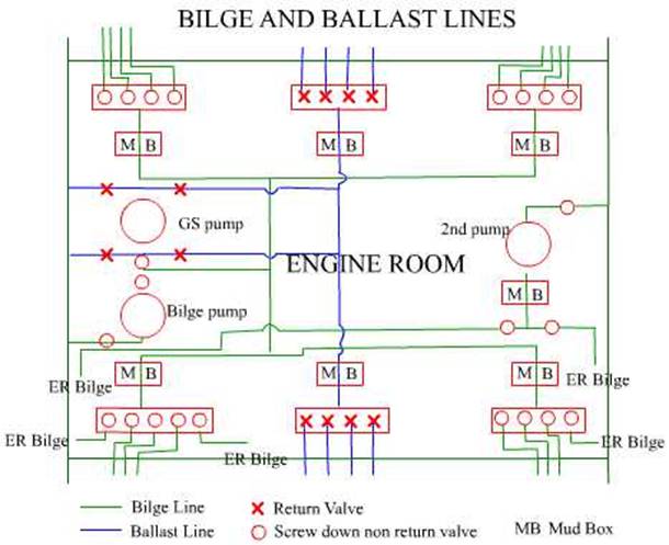
The strum box fitted in the holds is to be kept clean
and the perforations are to be checked that they are not closed due to muck and
rust.
Same with the mud boxes in the ER fitted into the
system.
Arrangement of a fire main
Capacity of
fire pumps
The capacity of the fire pumps is stated in SOLAS but
need not exceed 25m3 per hour
Arrangements of fire pumps and of fire mains
Ships shall be provided with independently driven fire
pumps as follows:
Passenger ships of 4,000 tons gross tonnage and
upwards at least three
Passenger ships of less than 4,000 gross tonnage and
cargo ships of 1,000 tons gross tonnage and upwards at least two
Cargo ships of less than 1,000 tons gross tonnage to
the satisfaction of the Administration
Sanitary, ballast, bilge or general service pumps may
be accepted as fire pumps, provided that they are not normally used for pumping
oil and that if they are subject to occasional duty for the transfer or pumping
of oil fuel, suitable change-over arrangements are fitted.
The arrangement of sea connections, fire pumps and
their sources of power shall be such as to ensure that:
In passenger ships of 1,000 gross tonnage and upwards,
in the event of a fire in any one compartment all the fire pumps will not be
put out of action.
In cargo ships of 2,000 gross tonnage and upwards, if
a fire in any one compartment could put all the pumps out of action there shall
be an alternative means consisting of a fixed independently driven emergency
pump which shall be capable of supplying two jets of water to the satisfaction
of the Administration. The pump and its location shall comply with the
following requirements:
The capacity of the pump shall not be less than 40% of
the total capacity of the fire pumps required by this regulation and in any case not less than 25 m3/h.
Number and position of hydrants
The number and position of hydrants shall be such that
at least two jets of water not emanating from the same hydrant, one of which
shall be from a single length of hose, may reach any part of the ship normally
accessible to the passengers or crew while the ship is being navigated and any
part of any cargo space when empty, any ro-ro cargo space or any special
category space in which latter case the two jets shall reach any part of such
space, each from a single length of hose. Furthermore, such hydrants shall be
positioned near the accesses to the protected spaces.
Pipes and hydrants
Mainly galvanised steel pipes are used and during
repairs no doublers or such part renewals are allowed – change is flange to
flange renewal.
The arrangement of pipes and hydrants are to be such
as to avoid the possibility of freezing.
On cargo ships where deck cargo may be carried, the
positions of the hydrants are to be such that they are always readily
accessible and the pipes are to be arranged, as far as practicable, to avoid
risk of damage by such cargo.
A valve is to be fitted at each fire hydrant so that
any fire-hose may be removed while the fire pump is at work.
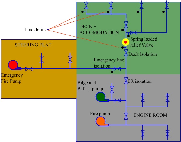
The above figure shows a typical fire mains line. Note
that the emergency fire pump is located away from the machinery space as per
rules.
Isolation valves are provided so that any system being
damaged the other system may be used for example the port system and the starboard
system.
In the machinery space a separate pump (Fire and GS
pump) is also coupled, this is generally used when washing decks, and as an
emergency measure while the fire pump is being overhauled.
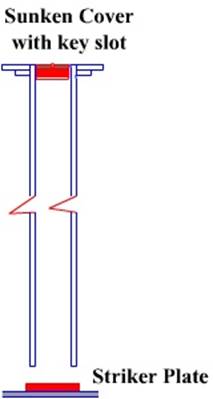
Sounding pipes
Sounding pipes covers come with varied designs. That
shown below is a sunken cap type generally the cap is made of brass. The
justification being that of the two thread and cap
assembly the thread of the brass is to wear out first and that of the deck pad.
The renewal of the brass cap being inexpensive and convenient
rather than the deck pad which entails hot work.
The metal cap (not sunken) type of
covers have a chain attached to them to prevent their being washed
overboard.
Air pipes to ballast tanks or fuel oil tanks
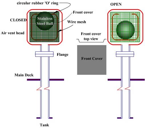
The above figure shows a design of air pipe cover.
In normal condition – the ball remains at the bottom
of the air pipe head and the tank breathes in and out through the vent.
However in the event that the air pipe is submerged
then the ball floats up and closes the opening at the top thus preventing any
water from entering the tank.
Sea spray and rain is prevented from entering the tank
by the design of the head. It is totally enclosed and a rectangular plate,
which leaves a small gap between the mesh and itself, allowing the breathing of
the tank.
Fittings
and lashings for the carriage of containers on deck
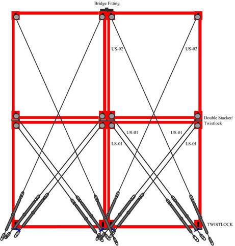
In the figure above the containers on deck are loaded on top of shoes
which are welded on top of the deck as well on top of the hatch covers.
Twistlocks are fitted
on the shoes and the containers placed on the twistlocks.
Hinged eyes are welded on deck to secure the container rod lashings.