Echo Sounder and Speed Log
Echo Sounder
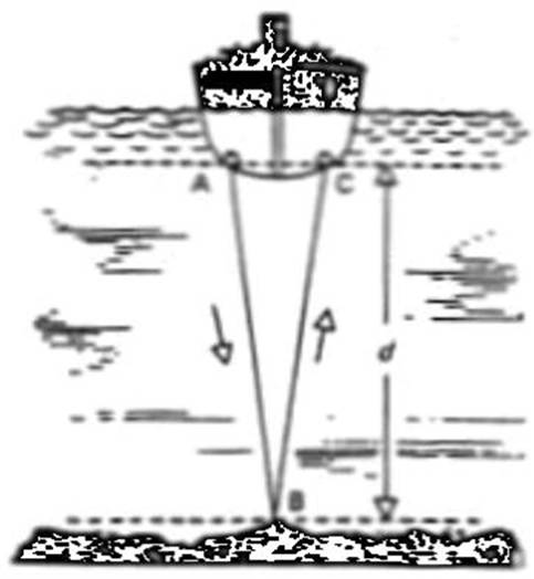
Basic Principle
Short pulses of sound vibrations are transmitted from
the bottom of the ship to the seabed. These sound waves are reflected back by
the seabed and the time taken from transmission to reception of the reflected
sound waves is measured. Since the speed
of sound in water is 1500 m/sec, the depth of the sea bed is calculated which
will be half the distance travelled by the sound
waves.
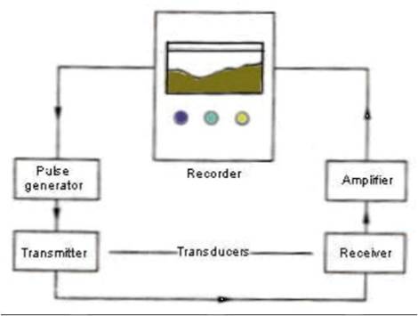
COMPONENTS
Basically an echo sounder has following components:
Transducer – to generate the
sound vibrations and also receive the reflected sound vibration.
Pulse generator – to produce electrical oscillations
for the transmitting transducer.
Amplifier – to amplify the weak electrical
oscillations that has been generated by the receiving transducer on reception
of the reflected sound vibration.
Recorder - for measuring and indicating
depth.
CONTROLS
An echo sounder will normally have the following
controls:
Range Switch – to select the range between which the
depth is be checked e.g. 0- 50 m, 1 – 100 m, 100 – 200 m etc. Always
check the lowest range first before shifting to a higher range.
Unit selector switch – to select the unit feet,
fathoms or meter as required.
Gain switch – to be adjusted such that the clearest
echo line is recorded on the paper.
Paper speed control – to select the speed of the paper
– usually two speeds available.
Zero Adjustment or Draught setting control – the echo
sounder will normally display the depth below the keel. This switch can be used to feed the ship’s
draught such that the echo sounder will display the total sea depth. This switch is also used to adjust the start
of the transmission of the sound pulse to be in line with the zero of the scale
in use.
Fix or event marker - this button is used to draw a line
on the paper as a mark to indicate certain time e.g. passing a navigational
mark, when a position is plotted on the chart etc.
Transducer changeover switch – in case vessel has more
than one switch e.g. forward and aft transducer.
Dimmer – to illuminate the display as required.
More on the principle of Echo Sounding
Echo sounder equipment makes use of sound (or sonic)
waves, which differ from radio waves in several ways. Sound waves vibrate in
the direction of travel of the wave front Sound wave velocity is comparatively
low (in comparison with radio waves). Sound waves can travel through a material
medium such as a gas, a liquid or a solid, but not a vacuum.
Sound waves can be produced over a very wide range of
frequencies, and these waves exert definite pressure variations, which under
certain circumstances can be measured. The audible frequency or frequencies
that human beings can detect varies, but an approximate range of detection
(also called as the normal range) can be considered as lying between about 20
Hz to 20,000 Hz. Those above the normal range of the human ear are termed
ultrasonic or supersonic frequencies.
There is a loss of energy when any waves are
transmitted through a medium and the losses increase as the frequencies
increase. Sound waves also suffer losses, however in
water such losses are of the order of 1000 times less as compared to the loss
in air. Supersonic vibrations are therefore much more suitable for transmission
in water than in air. The losses do increase due to high frequency,
however they do not become serious unless very high frequencies are used.
Water is an excellent sound transmitting medium as the
velocity of sound in the water is known accurately and it does not vary more
than about 3%, if temperature and salinity change.
The speed of sound increases as water temperature,
salinity and water pressure increases, and all of the above vary with depth.
The speed of sound varies from about 1432 metres/sec. in fresh water, to about
1535 metres/sec. in salt water of high salinity. For depth sounding equipment
design purpose a sound speed value of 1500 metres/sec. are assumed.
For normal applications on merchant vessels, the
indication of the depth value based on the average speed of sound (1500 m/sec.)
causes a minor error when changing from Salt Water (SW) to Fresh Water (FW).
Assuming there is a small correction adjustment for SW, the true depth in FW is
found to be about 3% less than the indicated depth. As can be seen, this
deviation is very small and thus insignificant for practical considerations.
When sound wave passes through an interface of two
mediums, besides suffering loss of energy, they refract as well as reflect
(critical refraction) at the boundary where the two media meet.
The Practice of Echo Sounding
The echo sounding principles is used as follows, to
measure depth. A short sound pulse is transmitted from the ship's bottom
towards the seabed where it is reflected back towards the hull as an echo.
The time interval between transmission of the pulse
and the receipt of the echo is measured, and the depth is found from the
expression:
Depth = velocity X time divided by 2
The frequency of the sound vibrations created in the
water during pulsing is usually at the upper end of, or above the audible
range. A depth sounder instrument can be obtained in three different forms
based on the transmitted frequency:
.1 using
14khz frequency (Low end sounders)
.2 using
14 kHz to 30 kHz frequency (Normal sounders)
.3 using
30 kHz frequency (High end sounders)
The choosing of frequency depends on the requirements
of the user. The chosen frequency is basically a compromise to avoid
interference from audible ship motion noise, and water losses through the
seawater.
Generally low frequencies are mostly affected by ship
noise and high frequencies by water losses, which are caused by absorption.
The sound pulses are created by transducers, which
convert electrical energy on transmission, and reverse the process when the
echo is received. The sound energy is always transmitted as a beam in a
particular direction (directional beam) and it would be very wasteful to permit
spherical radiation.
Transducers
are of two types:
Piezo-electric
transducer
Magneto-striction transducer.
Piezo-electric
transducer
This type makes use of the special properties of
crystals (e.g. crystals of barium-titanate and lead zirconate). If an alternating voltage is applied to the
opposite faces of a flat piece of one of the above materials, the crystal will
expand and contract, and hence vibrate creating sound waves for as long as the
vibrations continue. The process is reversible, i.e. when varying pressure from
a returning echo, is applied to the opposite faces, an
alternating voltage is generated across the faces and the same can be further
amplified and used to activate an indicator.
Magneto-striction transducer
In this type, the use is made of the magneto-striction effect which is a phenomenon whereby
magnetization of ferromagnetic materials produce a small change in their dimensions,
and conversely the application of mechanical stresses such as weak pressure
vibrations, as from an echo to them, produce magnetic changes in them; e.g. a
nickel bar when placed in the direction of or strength of the magnetic field.
If the nickel bar is placed in a coil with an alternating current flowing
through it (a solenoid), the varying current and magnetic field will cause the
ends of the bar to vibrate and hence create a sound wave. This is what happens
when the transducer is transmitting.
Type with specs 50 kHz - 100 W: Maximum depth
measurable - 700 metres Type with specs 20 kHz - 100 W: Maximum depth
measurable - 400 metres
The magneto-striction type
would be fitted inside a cast elliptical housing or a circular housing in such
a way that the bottoms of the pistons are in contact with the sea (i.e. pierced
hull type - see details of this type later).
Another type, which is fitted internally, consists of
a ring of thick nickel discs enclosed in a winding to which the AC is applied.
This resulting sound pulse is directed downwards through the steel bottom shell
by a reflector. The advantages of nickel ring types are that it is cheaper to
construct and damping is greater.
In both designs the sound pulses are directed down
wards in a cone shaped beam to avoid loss of sounding when the vessel is
rolling. The process is reversible, as, when the echo returns, it applies a
varying pressure to the working faces of the transducer, which causes the
magnetic condition of the nickel to fluctuate at the same frequency. This
varying magnetic field strength induces a voltage in the winding round each
piston leg and this voltage is amplified before being applied to the indicator.
As oscillators must be in
water dry forepeak tanks. Tanks may be flooded sufficiently
to-keep them submerged. Forepeak tanks are usually arranged so that when they
are pumped out, enough water is retained to keep the oscillators from becoming
dry.
Echo
sounding equipments may be divided into two main classes:
.1 Those that transmit and receive sound vibration through the
shell plating of a ship, referred to as 1nternal installation" class.
.2 Those
that are in direct contact with the sea generally referred to as
"pierced-hull installation" class.
In the internal installation class, because of the
shell plating, energy is wasted during transmission and reception. For a shell
plating thickness of 9.5 mm, about 15 per cent of the energy gets through the
plate and only 2 per cent gets through when the shell plating is 31.8 cm thick.
The advantages of having an internal installation are:
.1 Equipment may be fitted without dry-docking
the ship.
.2 Projectors
or oscillators may be serviced or changed while the ship is afloat.
Sound wave energy is wasted if it is required to pass
through a plate. The plate will prevent sound waves to pass through, if the
thickness of the plate is close to a quarter wavelength of the sound wave; but
if thickness of the plate is about a half wavelength then the steel plate
becomes transparent to the sound wave.
For a pierced-hull installation, the shell plating of
the ship is first pierced and the gap filled in by a thinner plate. If a steel
plate is to be fitted, then the physical dimensions of the steel plate needs to
be small and the plating will have to vary in thickness from ship to ship
because of different frequencies used.
Thus for pierced hull installation the problem of
using a frequency suitable for reasonable penetration no longer applies and
higher frequencies can be used.
With a very low frequency, the size of the oscillator
becomes inconveniently large; secondly, there is lack of selectivity from water
and other noises within the audible range and finally, less directivity.
The higher frequencies gives
more improved selectivity from noise and better directivity is possible, but
there is less penetration.
Echo Sounding - Full cycle of operation
The full cycle of operations for one sounding is as
follows:
The recording stylus starts each cycle as it moves
pass the zero. It triggers an electronic generator, which produces a known
number of electrical oscillations, which are applied to the transmitting
transducer (Tr/Tx). The Tr/Tx
creates the sound pulse, which is injected into the sea, travels to the bottom,
is reflected and returns as an echo to the receiving transducer, where it is
converted back into an electrical pulse. This is amplified and applied to the
stylus, which has moved across the recording paper, to indicate the depth
against a suitable scale. The stylus moves across the paper at a constant speed
which is decided by the designer after he has decided the following:
Maximum depth to be displayed,
Width of the paper and the
SW velocity to be used.
The pulse length to be used for transmission is
governed by a number of factors. The minimum theoretical depth that can be
measured is equal to half a pulse length. Since sound travels at approx. 1500
metres per second, a pulse length of 1 millisec (ms)
will mean that the theoretical minimum depth, which could be measured, would be
1.5 metres. In practice it would be about this value.
The difference between the theoretical and the
practical values is because the transducer being a resonant device does not
stop oscillating immediately the electrical pulse ceases. It shows a tendency
to "ring" when energised and this is usual
for the time taken for 10 to 12 cycles. If depths less than 1.5 m are to be
measured then a shorter pulse length is required. One sounder has a pulse
length of 0.3 m, which gives a theoretical minimum sounding of 0.225 m and a
practical minimum of 0.45 m.
If a very deep measurement is to be made then more
energy is required. This could possible be achieved by increasing the amplitude
of the pulse, but this is usually limited by the output of the active element
in the transmitter and therefore it is injected directly into the water.
Sounders, which have to cover very shallow and very deep sounding on different
ranges, will usually be designed so that the pulse length can be changed as the
range is changed.
PULSE LENGTH
Shallow 0.3
milli sec Up
to 200 or 400 metres
l to 5 milli sec 2000
metres or more
The commonest form of echo sounder has a display,
which records the depth on electro-sensitive paper. It may take the form of
rotating arm moving anti-clockwise across the paper, which is marked by the
stylus at the end of the arm when a DC pulse is applied on receipt of the echo.
Another type has a moving belt to which the stylus is attached and which is
made to move across the paper from top to bottom at a constant rate, which is
decided by the depth scale displayed. The paper is marked in the same way, and
the indicated depth is measured from the top of the paper by a suitable
vertical scale at the side.
Another type of display more suitable for shallow
depths consists of a disc or arm carrying a neon lamp at its extreme edge,
which is spun round at constant speed. A scale is fitted round the edge of the
area covered by the spinning neon which is made to flash at zero on
transmission and again on receipt of the echo at the point in its revolution
appropriate for the depth measured. The overall recording accuracy claimed for
one echo sounder is close to +/- 2% of the actual depth.
Recording Paper may be of two kinds, moist and dry.
The moist paper is impregnated with a solution of potassium iodide and starch.
When a direct current is passed through it from the stylus to the metal plate
at the back, it releases iodine and causes a brown stain to appear. The stylus
is tipped with iridium. This action only takes place when the paper is damp -
it becomes an insulator when dry.
This type of paper should be kept in its airtight tins
before use. If an echo trace on damp paper is to be kept for reporting or other
purposes, a line should be drawn down each side of the paper while it is still damp
to indicate the limits of the scale. The bottom trace and transmission line
should be drawn in pencil, the paper dried, preferably in a dim light, and then
the paper should be rolled up to prevent fading. An indelible pencil should
preferably be used or a ballpoint pen for all writing.
The Dry paper is a carbon impregnated paper base, metallised on one side and covered on the other with a very
thin film of fight coloured semi-conducting chemical. The metallised
side makes contact with the metal plate at the back, and the stylus moves over
the chemically treated side. When the echo returns, a pulse of current is
applied to the stylus which destroys the chemical film and exposes carbon
beneath to show a black record in contrast to the gray paper, carbon dust and
possibly fumes will be released and these may be a health hazard. The recorder
must be sited so that adequate ventilation its
possible. The dust, which is deposited on parts of the recorder must be removed
at require intervals using a soft rag or brush.
TRANSDUCER SITING
Satisfactory operation of an echo sounder depends on
the transmission and reception of the largest possible signal for a given
amount of power. The siting of the transducer is important in this respect to
reduce attenuation on transmission and reception as far as possible. The ideal
position is one in which there is "solid" water free from aeration
beneath the transducer, and where the effects of surface, engine and propeller
noise are at a minimum. There are few positions which are suitable in every
respect and a position found to be satisfactory in one design of ship will not
necessary give equally good results in another.
The principle source of aeration is the bow waves
created by the ship. This wave rises some way up the stem, curls over, and then
is forced down beneath the ship, taking a quantity of air with it.
The resultant bubble stream normally starts about a
quarter length of the ship from the stern, and divides about three quarters of
the length from the bow. The bubble stream varies in form and intensity
according to the speed, draught, shape of bow and hull, the trim of the ship as
well as the sea state. In ships with a bulbous bow the wave appears to dip
water just abaft the stem, so that the flow of bubbles is over almost the whole
length of the vessel and the only satisfactory forward site may be within the
bulb. In oil tankers the after position is invariably chosen, usually under the
fore part of the engine room. Classification Society Lloyd Register does not
permit oscillators to be fitted underneath cargo space on vessels classed for
carrying petroleum in bulk.
A position in the forepeak may appear to be the best,
but in bad weather and light ship it would be unlikely to give good results and
may also be difficult to fit there. In laden ship of normal design a position
about a quarter of the length from the stem will often be found to give
satisfactory results. Ships often making long passages in ballast e.g. tankers,
often find an after position about three quarters of the length from the stem
gives better results. If two are fitted, one is fitted at one quarter and one
at three quarter length abaft the stem.
Care must be taken to make sure a receiving transducer
is a sufficient distance from the propeller, and tests should be carried out to
ensure this. They need to be sufficiently separated to prevent interaction
between them, but the separation should be as small as possible to ensure
accurate sounding in shallow water. Positions either side of the keel is often
satisfactory.
Other factors, which should be borne in mind, are: fit
in a horizontal position, sometimes slightly projecting but faired off to avoid
aeration. Avoid sites near bow thruster units, water intake pipes and
underwater log units.
Internal access to the transducer should be possible
for maintenance. Any junction box should be in a dry space and if possible the
transducer should be in a dry place.
NOISE
All transmission systems are subjected to interfering
signals of some kind.
CROSS NOISE
It is caused by vibration of the energy, which is
transmitted out by a ship and goes directly to the echo sounder receiver. The
recorder shows a broad line on zero reading and this can mask echoes totally.
THERMAL NOISE
It is generated in electronic devices by random movement
of electrons in components and this is amplified in the receiver in any radio
system. In sonar system, using sonic waves below 50 kHz, noise level can
usually be ignored, as it is very small compared with the sea noise.
SEA NOISE
They are of two main kinds, the first are interfering
wave action, and may be thought of as background noise. Sources are fish, other
ships, and noise from one's own ship particularly in bad weather and close to
land. For most purpose, the amplitude of disturbances at any instances is
unpredictable and taken, as a whole may be considered random. For this reason,
the designer must make sure that the signal is always recognisable
above the noise level.
The second is noise produced by the interaction of the
sea and the sonar system. This is generally called "reverberation
noise" and when transmitted into water, all the small reflectors in the
water such as bubbles, marine life, and mud and sand particles immediately
affect it.
These multiple reflector produces a return signal (echo),
which is theoretically continuous since they exist at all depths. However the
intensity of the transmitted pulse is reduced as it moves away from the
transducer and the intensity of the return signal also reduces in accordance
with the same law. The result is that after the end of transmission, the
reverberation signal decreases with time according to an inverse square law.
Its effect can be considerably reduced by the use of time variable gain or
"initial suppression". This circuit is set to reduce the gain of the
receiver to a very low level immediately following transmission, but then
allows the gain of reverberation noise after the same has fallen below that of
background noise.
Interpretation of Sounding
False Bottom Echoes. Second
Trace Echoes
Echoes, which are received at a properly adjusted
sounder, until after the stylus has completed one or more passes across the
paper and the next pulse have been, transmitted cause false readings. Example
of one revolution represents 1600 metres, and an indicated depth of 50 metres
could be sounding of 50 or 1650 or even 3250 metres. The correct depth can be
ascertained if the transmission circuit can be switched off with the stylus
still moving. After switching off, on the switch and then count the number of
times the stylus crosses the paper before the echo re-appears.
Reflection echoes
a) Double Echoes
Echoes received after reflection from the seabed, but
which the hull or the sea surface back to the bottom and then reflects thence
to the transducer. They produce a second weaker echo at approximately double
the correct depth. It will fade out if sensitivity is reduced (may be received
up to several hundreds metres).
b) Multiple Echoes
Echoes received after being reflected several times
between the seabed and the surface or the ship's bottom before the energy is
lost. It causes equally spaced echoes on the trace. Reduce sensitivity to fade
out. Switch on to first phase and then phase deeper to locate first echo.
c) Variable Echoes
These are varying reflecting surfaces on the seabed.
In general hard sand, coral, chalk and rock are good reflectors and thick mud
is a poor reflector. Stepped formation of rock result in side Echoes from an
object not immediately below the vessel but whose slant depth is less than the
depth of water.
d) Electrical faults, or man made noises.
Other False Echoes
These do not normally obscure the bottom echo and may
be caused by
.1 Shoals
of fish
.2 Layers
of water of differing sounding velocities (salinity etc.)
.3 The
deep scattering layer, which is a layer or set of layers, in the ocean,
believed to consist of plankton and which attenuate, scatter and reflect sound
pulses. They lie between about 300-450 metres below the surface by day, and
near the surface between sunset and sunrise (by day, it is more pronounced when
the sky is clear, than when overcast).
.4 Kelp or weed.
.5 Turbulence from the interaction of tidal streams or
eddies with solid particles in suspension.
SPEED ERROR
The speed of the recorder motor must be proportional
to the velocity of sound in seawater and the velocity is known to vary. The
recorder motor running at an incorrect speed causes the speed error. If the
motor speed is too fast, it will record a greater depth and if it is too slow
than a lesser depth.
Other errors include Pythagoras error, error due to
maladjustment, ECHO SOUNDER CONTROLS
Mains
Dimmer
Range/Phasing/ scale
Gain
Other controls
Speed control
Zero adjustment/Draught setting
Change over transducer
Minimum depth alarm
PULSE length
Number of pulses per sec.
Checks on echo sounders
Twice yearly with hand lead, if reading is too high,
then motor is going too fast.
ERRORS
Velocity Error - Increase in temperature and salinity
of water increases velocity of sound in water thus giving rise to an error in
the depth displayed.
Aeration – Presence of air bubbles below the
transducer gives rise to false echoes. Air bubbles are normally caused when a
vessel goes astern, turbulence when rudder is put hard over or due to pitching
when vessel is in light condition.
Multiple echoes – This is caused in shallow waters
with a rocky bottom due to some of the sound pulses reflecting up and down
between the ship’s keel and the sea bottom before being recorded on the
display. The first echo is the correct reading.
False echoes – In deep waters, by the time the sound
pulse returns from the bottom, the stylus may have already finished more than one revolution and thus the
echo which will be recorded will be a false one and the depth indicated will be
much lower than the actual depth.
Pythagoras Error – If the vessel has one transducer
for transmitting and one transducer for receiving, separated by some distance,
the distance travelled by the pulse will be greater
than the depth of the sea bed in shallow waters.
MISCELLANEOUS
Comply with the maintenance instructions given in the
manual. Normally it is just a monthly
cleaning of carbon / dirt deposits from the inside of the recorder.
Keep a stock of at least 1 spare stylus and 3 months
stock of recording paper.
Compare the soundings obtained with the soundings
given in the chart.
Maintain a log to enter the soundings obtained.
Some echo sounders have an alarm to alert the
navigator when the sounding goes below the set sounding.