Compass Work
Gyro Compass
Free Gyroscope
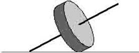
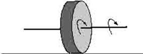
A wheel at rest A wheel in motion
A Gyroscope consists of a spinning wheel. The
important properties of this are its inherent gyroscopic inertia and
precession.
If a spinning wheel is free to turn about two axes at
right angles to each other and to the spin axis, it is said to be a free
gyroscope.
A free gyroscope, when spinning rapidly, possesses
considerable directional stability or inertia. That is it has
a great resistance to any tendency to change the direction in which its spin
axis lies.
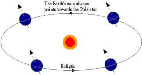
The earth too may be compared to a free gyroscope. The
earth’s spin axis lies in the direction of the ‘pole star’.
A spinning wheel can be made to approximate to a free
gyroscope by supporting the spin axis in gimbals. This way on gimbals the
centre of gravity of the wheel lies at the level of the gimbals axes and so
that the pivots are made frictionless.
However due to the placing of this gyroscope on the
surface of the earth, it will be moved along the direction of rotation of the
earth. As such the gyroscope will have an apparent motion.
For example, at night if the gyroscope is made to
point in the direction of a star, then the gyroscope will follow the star as
the earth rotates and the star apparently moves in the sky.
Precession
If a torque – a turning moment, in the plane of the
spinning wheel is applied to a gyroscope axis, the effect is only to increase
or decrease the rate of spin. The direction in which the spin axis lies is
unaffected.
If a torque is applied to a gyroscope axis in a plane
at right angles to the plane of spin, then the gyroscope becomes unbalanced.
And to restore the balance it moves in a direction at right angles both to the
plane of the spinning wheel and the plane in which the torque is applied.
This movement at right angles to the torque is known
as precession.
And a balance is achieved. This in much the same way
that a weight swung in a circle on the end of a string achieves a balance by
virtue of its movement at right angles to the string although the force acting
on the weight is along the length of the string.
The direction in which a gyroscope axis moves when a
force is applied to it depends upon the direction in which the wheel is
spinning.
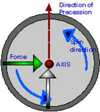
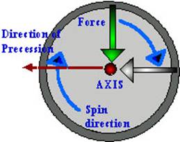
The direction of the precession due to a particular
torque may be predicted by imagining an arrow pasted on the gyroscope so as to
indicate the direction of the force, which causes the torque. If the gyroscope
wheel is the turned through 90˚ in the direction of spin, the new position
of the arrow will indicate the direction in which the gyroscope must precess in order to balance the applied torque.
The rate at which a gyroscope precesses
depends upon the weight of the gyroscope wheel and the way in which the weight
is distributed with respect to the axis. That is upon the moment of inertia (I)
of the wheel. The greater the torque (T) applied to the gyroscope axis, the
greater the rate of precession. The faster the rate at which the wheel spins
(S), the greater will be its momentum and the slower will be the rate of
precession. Combining the three factors the following formula is arrived at:
Rate of Precession = T / (S * I)
Northerly speed error
A gyrocompass is made North
seeking by a gravity control device which senses any tilting of the gyro axis
due to the Earth’s rotation. If the axis lies out of the meridian the end which
points to the East is sensed to be tilting upwards and the end which lies to
the West is sensed to be tilting downwards.
The gravity control precesses the gyro axis to seek a position in which
the rate of tilting is zero.
The rate of tilting due to the Earth’s rotation varies
as the sine of the azimuth and is therefore zero when the gyro axis lies in the
plane of the meridian.
Course, latitude and speed error arises because a gyro
axis is also caused to tilt by the velocity of a ship over the surface of the
Earth.
The East-West component of a ship’s velocity simply
adds to or subtracts from the effect of the Earth’s rotation, and acts in the
same plane.
The North-South component of the ship’s velocity
causes tilting in a plane at right angles to that caused by the Earth’s
rotation.
The gyro axis is tilted at a rate (in minutes of arc
per hour), which is equal to the North-South component of a ship’s speed in
knots.
If a ship is on a Northerly course the North end of
the gyro axis is tilted upwards. The control system, being unable to
distinguish between tilting due to the ship’s velocity and that due to the
Earth’s rotation, precesses the North end of the gyro
axis to the West, causing an error of this name (i.e. West).
For a ship on a Southerly course, the North end of the
gyro axis is tilted downwards by the ship’s velocity and the control system precesses the North end to the
East of the meridian.
For a ship heading North or South on a non-rotating
Earth a gyrocompass, seeking a position in which the rate of tilt was zero,
would settle with its axis East-West.
In practice the resultant settling position lies
between the meridian which it seeks in response to the earth’s rate of tilting
- 15˚x60’ cos. Lat. Minutes of arc per hour, and the East-West line which
it seeks in response to the tilting due to the North-South component of a
vessel’s speed (Speed cos. Course in minutes of arc per hour).
The error (A) may be found from a vector triangle.
Since it is a small angle, it is given in radian measure:
A = S. cos.
Course/900 cos. B
(S =
speed in knots, B = latitude)
Or in
degrees:
A˚
= (S. cos. Co./900 cos. B) x (180/Π)
A˚
= S. cos. Co./5 Π cos. B
In the above the East-West component of a vessel’s
velocity is small compared to the rotation of the earth and is therefore
neglected.
The name of the error is Westerly for ships on Northerly
headings and Easterly for ships on Southerly headings.
Rate of
precession:
The rate of precession of the gyro axis is
proportional to the applied torque. It is also inversely proportional to the
gyroscopic inertia of the rotor, which is expressed by the angular momentum
possessed by the rotor.
Thus
Precession α Applied torque / Angular momentum
P α T / H
Tilt
If a free gyroscope is situated on the equator and
lies with its axis East – West and horizontal, it can be assumed of as pointing
to a star with zero declination and is about to rise.
The
After nearly six hours the axis will be vertical and
after nearly twelve hours the gyroscope will have turned completely over with
the axis again horizontal but now the original East end of the axis would be
pointing to the star setting due West.
After one sidereal day, the gyroscope would have
tilted through 360˚ and the star would again be rising.
This rate of tilting of 360˚ in a day is a rate
of 15˚ per hour.
If the gyroscope had been situated on the equator with
its axis lying in the North – South direction, then the North end would be
pointing towards the Pole star and would then have no apparent movement
relative to the Earth.
The rate of tilting thus varies from zero when the
axis is lying North – South to a maximum when it is lying East – West. That is
the rate of tilting varies as the Sine of the Azimuth.
A free gyroscope situated at a pole with its axis
horizontal would have an apparent turntable motion due to the Earth’s rotation.
That is it would follow a fixed star around the
horizon but it would not rise or set.
The rate of tilting thus varies from a maximum when
the latitude is 0˚ to zero when the latitude is 90˚. That is the rate
of tilting varies as the Cosine of the Latitude.
The following formula gives the rate of tilting of a free
gyroscope at any instant, but note that the rate is constantly changing and the
value given by this formula cannot be taken over a considerable period of time.
Rate of tilting in degrees per hour = 15˚ sine
Azimuth * cosine Latitude
The direction of tilting is such that the end of the
gyroscope axis, which lies to the East of the meridian, tilts upwards and the
end of the axis, which lies to the West of the meridian
tilts downward.
Drift
Drift is the apparent movement of a gyroscope in
azimuth.
A free gyroscope situated at the North Pole with its
axis horizontal will have an apparent movement, which is entirely in the
horizontal plane.
Its axis will appear to move in a clockwise direction
when viewed from above. This would be due to the real counter clockwise
rotation of the earth beneath.
This circular motion causes the gyroscope to drift
through 360˚ in one sidereal day.
That is at a rate of 15˚ per hour.
A free gyroscope situated at the equator with its axis
horizontal will not drift at all, irrespective of whether its axis is set in
the North – South or East – West line.
The rate of drift for a gyroscope with its axis
horizontal thus varies from a maximum at the poles to zero at the equator.
That is the rate of drift varies as the sine of the latitude.
For a free gyroscope with its axis horizontal:
Rate of Drift in degrees per hour = 15˚ sine
Latitude
The direction of drift depends upon hemisphere so that
the North end of a horizontal gyroscopic axis drifts to the eastwards in the
Northern hemisphere but to the Westwards in the Southern hemisphere.
Gravity Control
A free gyroscope may be made North
seeking by attaching a weight to the rotor casing either above or below the
centre of gravity of the rotor. This so that when the axis lies horizontal the
weight is distributed equally between the two ends of the axis but when the
gyroscope is tilted the weight exerts more thrust on one end of the axis than
on the other.
This causes a torque in a vertical plane and the
gyroscope axis is made to precess horizontally.
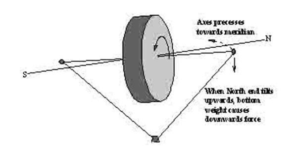
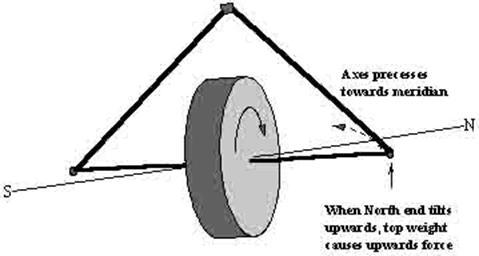
When one end of a gyroscope axis is to the East of the
true meridian, and if it is pointing at a rising star, then that end will
always tilt upwards. To cause this end to precess
towards the North if the gyroscope wheel is spinning clockwise when viewed from
the West, a downward force is required on the East end of the axis. This effect
can be provided, when the East end of the axis tilts upwards by suspending a
control weight below the gyroscope, thus making the rotor casing ‘bottom
heavy’.
To cause the East end of the axis to precess towards the North if the gyroscope rotor is
spinning anti-clockwise when viewed from the West, a downward force is required
on the West end of the axis. This effect can be provided when the East end of
the axis tilts upward, by supporting the control weight above the gyroscope,
thus making the rotor casing ‘top heavy’.
A gyroscope with gravity control as described above will not settle in the meridian. But the North-seeking end of the axis will tend to precess towards the meridian when it lies East of North and tilted upwards. Similarly it will also tend to precess towards the meridian when the North-seeking end of the axis lies to the west of North and is tilted downwards.
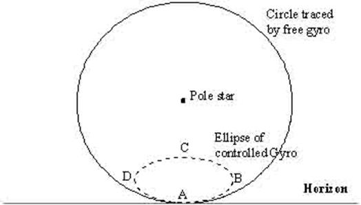
In intermediate North latitude, a free gyroscope set
with its axis North – South and horizontal has an apparent motion such that the
North end of its axis describes a circle round the celestial pole. The
projection of such a circle on a vertical plane to the Northward of the
gyroscope position is illustrated as the firm line in the diagram below.
The North seeking end of the axis of a gravity
controlled gyroscope, started in a similar position will trace out an
elliptical path as illustrated by a pecked line in the figure above.
At position A with the gyroscope axis horizontal the
gravity has no effect. The North end of the axis drifts Eastwards
and tilts upwards, initially at the same rate as the free gyroscope. When the
North end of the axis has tilted above the horizontal the gravity control
causes precession towards the West.
This effect at first is not as great as the natural
drift towards the East and merely slows the Easterly movement. But later (at
position B) the rate of precession becomes equal and opposite to the rate of
drift and thereafter as the axis continues to tilt upwards, the axis moves
towards the West.
All the time the axis lies to the East of the
meridian, the axis is tilting upwards so that the greatest tilt and hence the
greatest rate of precession occurs when the gyroscope axis has returned to the
meridian (C).
Once the North end of the axis has precessed
to the West of the meridian the rotation of the earth causes it to tilt
downwards and the rate of precession decreases until at position (D) the rate
of precession is again equal and opposite to the rate of drift.
Thereafter the axis moves Easterly with a continuing
decrease in tilt until the axis again crosses the meridian at its original
starting point.
The time taken for a gyroscope axis to trace out a
complete ellipse depends on the degree of control, which is provided, but it
will always be less than the sidereal day which is required for a complete
circle of a free gyroscope. The period of commercial gyroscope compasses is
often chosen as 84 minutes.
The size and proportions of the ellipse depend upon
the starting position of the gyroscope and the degree of control. In practice
the gravity control is such that the ratio of the major axis of the ellipse to
the minor axis is very large. That is the ellipse is very wide in proportion to
its depth. For the purpose of explaining the ellipse height was increased.
Damping
In order to respond to the drift, tilt and precession,
which make it North seeking, the suspension of a gyroscope must be virtually
frictionless. A gravity-controlled gyroscope as described above would then oscillate
indefinitely on either side of the meridian.
In order that the oscillation shall become smaller
with each cycle so that the gyroscope axis finally settles in the meridian,
some form of damping other than by friction is required.
Damping in tilt means that when the North-seeking end
of the gyroscope axis is tilted a damping torque is applied in a horizontal
plane in such a direction that the resultant precession in a vertical
plane causes the tilt of the axis to decrease.
As the tilt of the gyroscope is decreased so the
precession in azimuth becomes progressively less and the
gyroscope spirals in from its starting position to a final settling position as
shown.
Damping in azimuth is achieved by introducing a torque
in a vertical plane, which causes a precession opposite to the gravity control
precession but out of phase with it, i.e. with a time delay. The resultant
precession in a horizontal plane causes the axis to overshoot the meridian less
each time it crosses it until the gyroscope axis reaches its settling position.

Making of a free Gyroscope into a North
seeking Compass:
A free gyroscope we know after it is set spinning will
continually have its axis either tilting or drifting or doing both if left
alone on the surface of the earth. So it is of no use to us to have such an
instrument.
The first step in converting a free gyroscope into a
compass is to make the axis north seeking. This is done by creating a torque
about the horizontal east west axis, which is effective when the gyro tilts out
of the horizontal.
This torque will produce a precession in azimuth, which causes the axis to seek the meridian (north south alignment).
Top-heavy
control:
In the figure above the rotor is supported through the
spin axis bearings. A weight is placed on top of the rotor casing such that
when the spin axis is horizontal the vertical through the centre of gravity of
the weight passes through the centre of the rotor.
In this condition the weight will produce no torque on
the rotor and is completely ineffective.
The spin axis if initially horizontal will not remain
so, since the rotation of the earth will cause the spin axis to develop a tilt.
If the axis is directed towards the east of the
meridian then that end will tilt upwards.
As that end tilts upwards, the weight comes into
effect; the centre of gravity of the weight will now instead of passing through
the centre of the rotor will now cause a torque about the horizontal axis,
which tends to topple the gyro even further out of the horizontal.
This effect is as if a force was applied to the south
side of the rotor casing at the bottom.
If this point is imagined to be carried 90˚
around in the direction of spin, which is anticlockwise as viewed from the
south, it will be evident that the spin axis will precess
in azimuth such that the north end moves to the west, that
is towards the meridian.
This precession is called control precession.
The direction of spin of the rotor must be in such a
direction as to produce a westerly precession of the north end of the spin axis
when that end is tilted upwards, and an easterly precession of that end when it
is tilted downwards.
Considering the above, however it should be understood
that the control precession will not always be directed towards the meridian.
As long as the north end of the spin axis is tilted upwards the precession will
carry that end towards the west.
The precession will continue even after the axis has
passed to the west of the meridian and will then be carrying the north end away
from the meridian.
Similarly when the north end is tilted downwards and
directed to the east of the meridian there will be an easterly precession
taking that end away from the meridian.
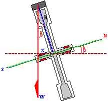
In the figure we see a top heavy controlled gyro with
the north end of the axis tilted upwards by β° (positive tilt).
The control weight exerts a moment about the
horizontal axis equal to Wx.
And
precession = applied torque / angular momentum
Thus
precession = Wx / H
And
x = h
sine β
thus
precession = Wh sine β / H
Let the constants W and h be expressed by the one
constant B.
Then
precession = B sine β / H
The negative sign is necessary to comply with the
convention that a precession upwards or eastwards is positive, and a precession
downwards or westwards is negative.
If the tilt β is small, as is the case with a
gyrocompass then
precession = B β / H
Where β is the tilt is in radians.
Therefore as both B and H are constants determined by
the construction of the gyro, it may be said that the precession is directly
proportional to the tilt β
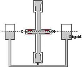
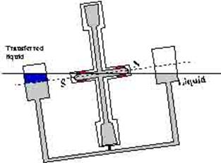
The control of a gyro by solid control weight is not used in practical compasses. Commonly used is a gravity control by a liquid ballistic, which flows between the north and south sides of the rotor under the influence of gravity, when the gyro axis tilts due to the earth turning.
In the above figure the above is shown the liquid used
is mercury because of its high density. The pots or bottles are also connected
at their top ends so that there is equalising of
pressure.
The system of pots and the rotor is arranged in such a
way that the centre of gravity passes through the centre of the rotor and that
the liquid levels are same when the axis is horizontal.
Thus there is no torque when the axis is horizontal.
In the second figure, the north end of the axis has
tilted upwards and so the mercury will get transferred to the south control
pot.
This imbalance will now cause a torque about the
horizontal east – west axis, which is transmitted to the rotor via the link to
the rotor casing.
The above effect is as if a force were exerted on the
rotor at the bottom of the south side. This is identical to the action of the
top mounted control weight, thus this effectively constitutes a top heavy gyro
compass.
The spin must be anticlockwise when viewed from the
south in order to create the required westerly precession when the north end
tilts up.
Damping the
Controlled Ellipse:
The controlled gyro will never settle in the meridian.
It will only oscillate about the meridian.
Only in one position will the gyro axis remain
pointing in a constant direction, if initially set there, and that is pointing
north with a tilt such that the control precession is equal to the drifting.
Precession thus cancels the drifting and there is no
tilting in the meridian. This will require a tilt of the north end upwards in
north latitude and downwards in south latitude.
The tilt necessary will increase with increasing
latitude. This position however is an unstable position and any slight
deviation from it will result in the axis commencing an elliptical oscillation.
And it will not return to the equilibrium position.
If the above controlled gyrocompass is used therefore
we see that it will never point north and even if it does it will not be stable
and will start to oscillate.
Damping means the process by which these oscillations
about the meridian will grow lesser and lesser until the axis is pointing along
the meridian and even if destabilised will return to
the meridian.
Damping may be achieved by the provision of:
A precession in azimuth (towards the meridian), or
A precession in tilt
(towards the horizon).
Damping in
Azimuth:
The amplitude of oscillations may be reduced by having
a precession in azimuth.
That is a precession towards the meridian.
Such a precession is similar to the control
precession, but in order to damp the controlled ellipse it must act with the
control precession.
When the control precession is directed towards the
meridian the damping precession acts with it. And when the control precession
is directed away from the meridian then the damping precession acts against the
control precession.
Thus the motion of the axis towards the meridian would
be increased and the motion of the axis away from the meridian would be
reduced.
With a rotor rotating clockwise when viewed from the
south:
The control precession is produced by a bottom heavy
effect while
The damping precession is produced by a top-heavy
effect.
The resulting precessions would therefore be in
opposite directions.
A gyrocompass damped in azimuth settles with the spin
axis aligned with the meridian but with a small upwards tilt of the north end
in the northern hemisphere, and a small downwards tilt of that end in the
southern hemisphere.
The gyrocompasses damped in azimuth are not subject to
the latitude error.
Damping in
Tilt:
To create a precession in tilt (horizontal east – west
axis) a torque about the vertical axis is required.
Latitude
Error – Damped in tilt:
The design and construction of the individual compass
will determine the magnitude of this error.
The errors are general controlled by a turning knob on
the gyrocompass control panel and has to be set depending on the latitude the
vessel is in.
The damping error is proportional to the tangent of
the latitude, as the latitude approaches 90° the tangent approaches infinity.
The error maybe large in higher
latitudes, typical values are:
Latitude 45° - 1.5°
Latitude 60° - 2.5°
Latitude 75° - 5.0°
Course
Latitude and Speed Error:
The compass will settle with respect to a false
meridian if the vessel is moving with a velocity, which has a northerly or a
southerly component. Such a movement would produce a false tilting of the spin
axis.
However if the movement were in the east – west
direction then this would not occur.
The error is given by:
Error
in degrees = (velocity x cosine course) / (5 π cosine latitude)
Damping using electrical signals
In more practical gyrocompasses, the liquid bottles
are dispensed with. Instead signal sensors operate servomotors, which provide
the required torque.
The gyro sphere is placed in a circular sphere and the
interwining space is filled with a liquid which has a
specific gravity that makes the gyro ball floating within the sphere a neutral buoyancy.
The torsion (tension) wire connecting the sphere to
the gyro ball is passed through a flexible conducting tube(
to pass the current)
Whenever the sphere is tilted the torsion wire is
stretched a current is induced in either the vertical or horizontal coils on
the outside of the sphere, the phase of the current depending upon the
direction of displacement. This signal is amplified and fed to a tilt or
azimuth servomotor which drives the gearing attached to the outside of the
sphere in such a way that the sphere is re-aligned with the gyro ball.
Settling in
Normally the torsion wire is not supposed to have any
twist or stretch, however from a cold start, the twist
to the torsion wire may be manually injected so that the gyro starts off in a
approximate direction as required. This reduces the settling time.
Period of settling differs between different
manufacturers. However the usual settling time is between 84 to 120 minutes.
The period
of oscillation of the controlled ellipse:
The period in which the axis completes one oscillation
in the controlled ellipse depends upon the magnitude of the control precession,
and upon the magnitude of the drift.
The drift depends upon only the latitude, but the
precession is determined by the factors B and H.
In practice gyrocompasses are designed with periods
from about 80 minutes to 120 minutes. Commercial gyrocompasses have a period of
about 84 minutes.
The expression for the period of oscillation (T), is given by:
T = 2
π √ {H / (B Ω Cosine Latitude)}
Here Ω is the rate of the earth’s rotation in
radians per second.
Controls
Latitude: Except at the equator the gyroscope will
have a drift. As the ship moves away from the equator a signal is injected into
the tilt servomotor producing a precession in azimuth equal but opposite to the
drift rate. The strength of the injected signal is determined by a control
knob, which can be set to any required latitude.
Course, latitude and speed error: The tilting of a
gyroscope axis in the East-West plane is used to make the gyroscope north
seeking. The upwards/ downwards tilting of the north end of the gyroscope axis
due to the North/ South component of a vessels’ speed causes course, latitude
and speed error.
Again as in the above a signal is manually injected to
the servomotor to tilt the gyroscope, this eliminates the above errors. This
manual signal is determined by setting a knob.
Repeaters
Transmission to repeaters is achieved by causing the
azimuth motor to drive a step by step transmitter which keeps the repeaters in
step with movements of the gyro sphere hence with the movements of the gyro
ball itself.
While adjusting the repeaters, the step transmitters
are to be switched off and the repeater tilted upside down. At the base a cover
is shifted to open a square spindle head. A special tool rotates this and the
course adjusted with that of the master compass. Once the heading is the same
the transmitter switch is put on.
Alarms and Indicators
Temperature alarm – generally set to a maximum of
62degrees Celsius, the blower which keeps the gyro cool cuts in at about 51
degrees.
Phase indicators.