Steering and Control Systems
Fluxgate Compass
Fluxgate compass
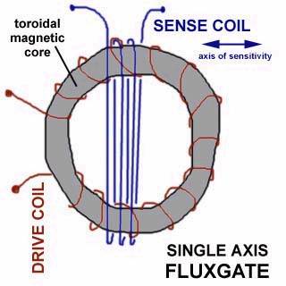
The fluxgate is one kind of magnetic field sensor
which combines good sensitivity with relative ease of construction. The basic
principle is to compare the drive-coil current needed to saturate the core in
one direction as opposed to the opposite direction. The difference is due to
the external field. Full saturation is not necessary; any nonlinearity will do.
As the core approaches saturation, the signal picked up in the sense coil will
show the nonlinearity. For instance, if you put a sine-wave into the drive
coil, the sense coil would detect harmonics of the fundamental frequency;
increasing in strength relative to the fundamental as the core becomes more
fully saturated.
Fluxgate compass
Different from the course detector that picks up the
magnetic field from the compass card magnet, the fluxgate compass picks up the
Earth’s magnetic field directly.
The sensor coil is either mechanically gimballed or has a floating ring core .
This will prevent an uneven distribution of the magnetic field in the sensor
coil when the boat is rolling and pitching. Compared to a magnetic compass,
however, the fluxgate compass is more sensitive to the motions of a vessel. In
rough sea conditions or in sharp turns at high speeds, the sensor may be
temporarily displaced from the horizontal plane.
A distorted and unstable heading input to the
autopilot is the resulting effect. A lot of attention has been paid to reduce
this effect when designing the Fluxgate compass and it has proven to be
successful. The optimum performance is accomplished with a rate sensor
stabilized fluxgate compass.
Except from the Rate Compass, fluxgate compasses are
not recommended as autopilot compass on steel boats, mainly due to lack of
efficient “heeling error” compensation. This compensation is needed when a
magnetic heading sensor is mounted on top of the wheelhouse or in the mast.
The Rate Compass is in principle a combination of a
solid state rate sensor and a fluxgate sensor, where the rate sensor is slaved
to the fluxgate sensor.
The rate sensor will momentarily pick up any angular
changes in azimuth, but is almost unaffected by roll and pitch.
As the “rate heading” will drift, the fluxgate sensor
is needed to maintain the (magnetic) heading. However, as the rate sensor is
the primary “heading” source, the fluxgate signal can be more dampened and thus
it will not contribute to the instability caused by heavy rolling and pitching.
The Rate compass gives a more stable and precise autopilot
steering on any type of boat. It also eliminate the
effect of the distorted horizontal magnetic field at high latitudes and the
well known swing phenomena when on autopilot steering.
It can also be used as “stand alone” compass to
provide a stable heading input to a compass repeater, a radar
or other equipment.
However, care should be taken when using it on bigger
steel boats that can have strong local disturbing magnetic field that makes a
good calibration of the fluxgate impossible.

Explanation
to Block diagram
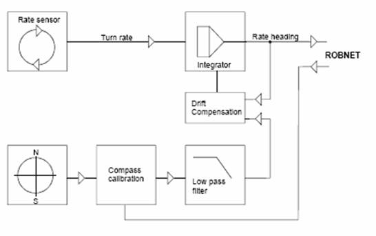
Refer to above figure.
The rate sensor generates a rate of turn signal that
is converted to a heading angle by the integrator circuit. This output is
called Rate heading.
The heading output from the fluxgate sensor, is called
Flux heading. It is filtered by a low pass filter with a time constant.
The Flux heading is calibrated and calibration data
are stored in the EEPROM in the compass.
The high dampening of the Flux heading will suppress
unstable heading signals caused by the vessel's roll and pitch.
The reduced response from the Flux heading is
compensated for by the Rate sensor. The Rate sensor is very sensitive to any
movement (turn) in the horizontal plane, but almost insensitive to roll and
pitch.
As the Rate heading is a relative angle it has to be
coupled to the Flux heading.
This coupling is made in the Drift Compensation
circuit which serves two purposes;
1. It will prevent the Rate heading from drifting away
due to internal (temperature) drift in the Rate sensor.
2. When a big course change is made and there is a
difference between the integrated Rate heading and the measured Flux heading,
the difference will be coupled into the Rate integrator as a bias offset for
the Rate heading to make it equal to the Flux heading.