ARPA
Stabilization
Loss of
sensor input
One occurrence, which will activate a warning, is the
loss of sensor input such as arises if log or gyro compass data is
missing. It is important here to note
that the ARPA has no way of knowing what values to expect and so can only warn
of their absence.
(The warning ‘log error’ means that the ARPA is
receiving no input from the log, and not that the value it is receiving is in
error.)
Use Of
Raster Scan Marine Radar Displays
The attention of Mariners is drawn to recent research
which has highlighted the possibility of misleading or erroneous displays
occurring with Raster Scan Displays (RSD) that suffer from the loss of certain
input signals. These problems are said to occur in two areas; loss of video
input and loss of azimuth signal.
The research showed that in some cases loss of video
input resulted in freezing of the picture, an effect not noticed until the
range is changed. The cause appears to be related to the fact that the screen
image is generated by a video processor and if the signal is lost, the display
does not redraw or refresh.
In other instances, the loss of azimuth signal led to
rotation of targets or targets being depicted on wrong bearings.
In many cases, the RSD did not display an alarm, or
indicate in any way that there was a problem with signal input.
Mariners should investigate the type of RSD fitted to
determine the response of their system to loss of input, particularly video and
azimuth signals. If no warnings are displayed in these circumstances, then
procedures should be developed to periodically test the integrity of the
display.
Mariners should contact the manufacturer of the
equipment for advice in detecting input failures and guidance in developing
test procedures.
The above is particularly important for operators of
high speed craft; with the limited response times on these craft meaning that
early detection of system faults is imperative.
Further information can be obtained from the research
paper, reprinted below from Focus,
Track
change
This alarm quantifies departures from the predicted
tracks of targets. The target(s)
activating the alarm will be indicated.
If all the targets generate the track change alarm
then it becomes obvious that the alarms were activated by large or rapid
manoeuvres performed by own vessel. In general, this condition can be
recognised, as all targets will exhibit the track change symbol.
Anchor
watch
This alarm is generated to offer automatic warning of
own vessel or other vessels dragging in an anchorage. If a known stationary target (for example, a
small isolated navigation mark) is acquired and designated as such then an
alarm will be activated if the designated target moves more than a preset
distance from the marked position. If
the stationary target appears to move, then it must be due to the own vessel
dragging her anchor.
Alternatively, it will also give a warning if another
‘tracked’ vessel in the anchorage moves away from the anchorage.
Tracks full
Since there is a limit to the number of targets, which
an ARPA is capable of tracking, in areas of high traffic density, there may
well come a time when all the tracking channels are in use. This is particularly likely when automatic
acquisition is in operation. An alarm
will warn the operator to inspect the untracked targets for potential dangers
and to transfer tracking from less important targets, which are being tracked
to the potentially dangerous ones (not as yet tracked).
Wrong or invalid request
Where an operator feeds in incorrect data or data in
an unacceptable form, e.g. course 370˚, an alarm and indicator will be
activated and will continue until the invalid data is deleted or overwritten.
Time to
maneuver
Where a ‘delay’ facility is provided with trial
manoeuvre, an alarm may be provided to alert the observer, to the fact that,
say, one minute until time to manoeuvre’.
Safe limit
vector suppression
This facility, if selected, suppresses the vectors of
targets whose predicted motion does not violate the safe limit and is an
attempt to reduce ARP ‘clutter’.
The ARPA continues to track the target whose vectors
are suppressed. If any of them should
manoeuvre in such a way as to violate the set safe limits, the vector of that
target will reappear and the safe limit alarm will be activated.
If a decision is taken to use this facility, be aware
to switch off the facility before contemplating a manoeuvre.
Trial alarm
This facility is the same as the safe limit alarm but
operates only when the trial manoeuvre is selected. It is not available on all systems.
Automatic
ground-stabilization
An isolated land target (lighthouse with a Racon) with
good response is selected as reference.
It is acquired and tracked by one of the ARPA tracking channels and then
designated as a fixed target. This makes
it possible for the tracker to calculate the ground track of own vessel and
hence to maintain the movement of the electronic origin of the display in
correlation to it.
When using this facility the observer should be
particularly watchful for other targets, which approach the reference target,
and, in particular, for those which pass between the observing vessel and the
reference target. If the target moves
too close to the ‘echo ref.’ target chances of target swop may be greatly
increased.
In general the same stabilization is applied to the
radar picture presentation and to the true vectors, i.e. either both are
sea-stabilized or both are ground-stabilized. Thus in general, where automatic
ground-stabilization is selected, true vectors will indicate the ground tracks
of targets and not their headings.
Failure to appreciate this can render the presentation
dangerously misleading if it is mistakenly used in the planning of collision
avoidance strategy.
One might expect the danger of observers being misled
in this respect to be less than in the case of a raw radar display because,
except in case of an along-track tide, there will be angular displacement of
own vessel’s vector from the heading marker.
The above makes it possible to have true-motion
parallel indexing. It also makes it possible to maintain electronic navigation
lines and maps in a fixed position on the screen.
However, it must be stressed that the presentation may
not afford traffic heading information
and may therefore in principle be unsuitable for collision avoidance.
Automatic ground-stabilization can also be achieved by
using the output from a twin axis Doppler log that is locked to the ground or
feed from the GPS.
Sea
Stabilized:
Whenever ARPA is used in the True track mode, data
relating to own vessel’s motion is fed in from the speed log and from the
gyro/magnetic compass.
Assuming that the speed log is feeding in the vessel’s
speed through the water and is not on
the ‘bottom lock’ mode, then the
displayed true track of the vessel would be sea stabilized.
Vectors would therefore indicate the true track through the water of other
vessel’s as well and thus would also the visual aspects of the other vessel’s,
irrespective of ant tide/current experienced.
IT IS THEREFORE VERY IMPORTANT THAT WHEN ARPA IS USED
IN THE TRUE TRACK ANTI COLLISION MODE, THAT IT IS ONLY USED IN THE SEA
STABILIZED MODE.
The above
is the reason that in spite of a vessel being equipped with a GPS receiver, it
is compelled by regulation to carry an operational speed log. The ARPA
has to have a feed from the speed log.
Ground
Stabilized:
Coastline drift may be prevented by feeding in the set
and drift due to the current/tide, or by having the feed come in from the speed
log working on ‘ bottom lock’ condition. Or also by incorporating the CMG
obtained from the GPS.
Another way is to have the facility of ‘echo reference’ lock on to a stationary
target (selection of the same requires utmost care, and is not recommended for
the novice).
Under the above the display becomes ground stabilized.
The displayed vector will then indicate the targets true tracks. Of course due
to the potentially misleading effect of the data relating to the tracked vessel’s
aspect, this mode should not be used when assessing collision risk or planning
avoidance strategy.
There are advantages of using either a True or a
Relative motion display. Relative motion displays and subsequent plotting gives
an immediate indication of which ships are on a collision course.
On the other hand, whether a target is stationary or
moving can be usually distinguished more readily with a true motion display.
Generally any one of the displays may be used, however
with the inherent advantage for collision avoidance, relative motion maybe more
suitable for open sea condition for collision avoidance.
Now regarding whether to use Ground stabilization or
not.
Well ground stabilization display may and will give a
misleading idea about a target/ship in coastal areas, involving tidal currents.
GPS speed in general gives ground speed, and there
lies the necessity of having a speed log, which can give input to the Radar of
the set and drift experienced by own vessel.
In the following example the same is highlighted:
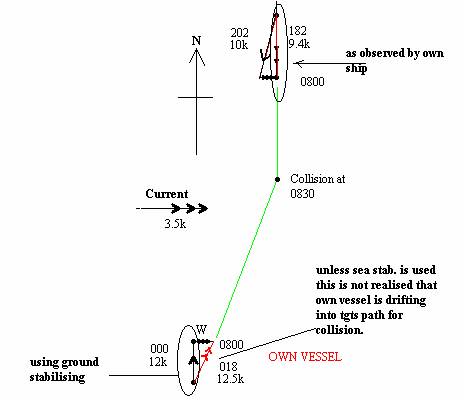
The
above is a case of an own vessel observing another target in an area where the
current is a factor. If ground stabilization is used, then the own vessel
course is taken by the ARPA as 000 deg. And speed of 12k, however due to the
current the actual vector of own vessel is
Thus unless sea stabilisation is used, the plot will
give a totally erroneous result and will seem that the vessels are passing
clear when actually they would be colliding.
This necessitates the use of a speed log as is
mandatory under SOLAS.