Electronic System of Position Fixing
Loran C System
INTRODUCTION
The term “Loran” is an acronym for LOng
RAnge Navigation (LORAN).
Loran-C provides better than 0.25 nautical mile (460 meters), absolute accuracy for suitably equipped
users within the published areas.
Users can return to previously determined positions
with an accuracy of 18 to 90 meters using Loran-C in the time difference
repeatable mode.
STATIONS
Loran-C transmitters are organized into chains of 3, 4
or 5 stations. Within a chain, one station is designated “Master” (M) while the
other “Secondary” stations identified by the letters W, X, Y and Z. Different
secondary designations are used depending on the number of station in a chain.
This is summarized in the table below.
|
CONFIGURATION |
DESIGNATORS |
AN
EXAMPLE |
|
Master with 5 secondaries |
M V, W, X, Y, Z |
South |
|
Master with 4 secondaries |
M W, X, Y, Z |
|
|
Master with 3 secondaries |
M X, Y, Z |
Canadian West Coast 5990 |
|
Master with 2 secondaries |
M X, Y |
|
Power levels can range from as low as 11 KW to as high
as 1.2 MW.
In
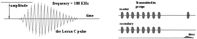
The Loran-C navigation signal is a structured sequence
of short radio frequency pulses on a carrier wave centered at 100 kHz. All
secondary stations send pulses in bursts of eight, whereas the Master signal,
for identification purposes, has an additional ninth pulse burst.
The sequence of signal transmissions consists of a
pulse group from the Master (M) station followed at exact time intervals by
pulse groups from the secondary stations.
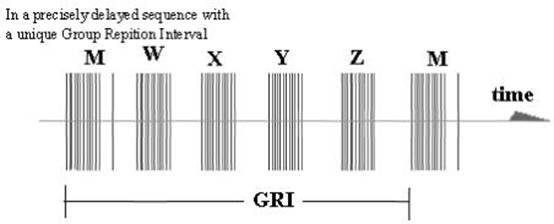
The time interval between the reoccurrence of the
Master pulse is called the Group
Repetition Interval (GRI).
Each Loran-C chain has a unique GRI.
Loran-C pulse structure and
sequencing.
Since all Loran-C transmitters operate on the same
frequency, the GRI is the key by which a receiver can identify and isolate
signal groups from a specific chain.
In naming the chains, the GRI is included. As an
example the
This means the time interval is 89700 microseconds.
The rightmost zero is always implied and the GRI is
always in multiples of 10 microseconds.
In old Loran-C receivers, the operator had to actually
set this number to receive the chain.
GRI’s are chosen
on the basis of:
Baseline lengths between
master and secondaries. If the
distance between the master and first secondary is say 1000 kms,
the radio signal will take 33,000 microseconds to get to the slave so the GRI
cannot possibly be less than that.
Number of slaves that have to be accommodated - they
all have to have delays so that there is no possibility of them crossing over
anywhere in coverage area.
Geography.
Other nearby chains with
consideration given to interference.
Skywave cross-rate interference.
Duty
cycle of the transmitters - a faster GRI means the average power of the
transmitted signal is higher so the final stage in the transmitter requires
more cooling. With average baseline lengths and three slaves, the minimum GRI
cannot be much less than 50,000 microseconds.
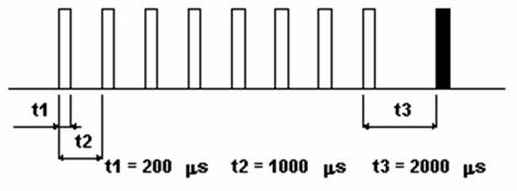
Each Loran-C pulse has an approximate duration of 200
microseconds (μs).

The
interval between pulses within a pulse group is 1000 μs,
except for the last two pulses at the Master, which have a 2000 μs interval.
1000 μs 1000
μs 1000
μs 1000
μs 1000
μs 1000
μs 1000
μs 2000
μs
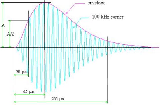
This above illustrates the points on the Loran-C pulse
envelope that define the start time, the time of maximum envelope power and the
stop time of the pulse.
Two other important characteristics are associated
with Loran-C signals, namely emission and coding delay.
If the master station is taken as a reference, the
emission delay refers to how long it takes before the secondary transmits after
the Master has done so.
The coding delay is a very small correction that
removes the local (near-field) discrepancy between the envelope and carrier.
Both parameters are measured in microseconds and are
uniquely associated with each secondary station.
BASELINES
AND COVERAGE
An imaginary line drawn between the Master and each
secondary station is called the baseline.
The continuation of the baseline in either direction
is called a baseline extension.
Typical baselines are from 1200 to 1900 km (say 600 to
1000 nautical miles).
Chain coverage is determined by:
The power transmitted from each transmitter in the
chain,
The distance between them and
How the different transmitters are oriented in
relation to each other (the geometry of the chain).
SKY WAVE
REJECTION
A frequency of 100 kHz was chosen for the Loran-C
carrier wave to take advantage of propagation of the stable ground wave to long
distances.
However, the presence of delayed sky waves, reflected
from the ionosphere, cause distortions of the pulse
shape and change the carrier phase within the pulses of the received signal.
Not only those, the skywaves
take longer to arrive at the receiver than the ground wave, so their presence
complicates the computation.
To avoid sky wave contamination, the Loran-C receiver
selects a zero crossing of a specified carrier cycle at the front end of the
pulses transmitted by master and secondary stations.
Making the cycle selection early in the ground wave
pulse - usually the third cycle is employed - ensures that the time interval
measurement is made using the uncontaminated part of the pulse.
But how is the third peak selected when the start time
of the pulse is not known?
To solve the problem, the receiver compares the
envelope (the rough shape) of the received pulse with a stored envelope.
This process is called the “rough measurement”. When
the third peak is finally located, the phase of the signal can be determined.
The phase of the signal can be zero or pi
radians.
Precise control over the pulse shape at the
transmitter also ensures that the selected zero crossing can be identified
reliably by the receiver.
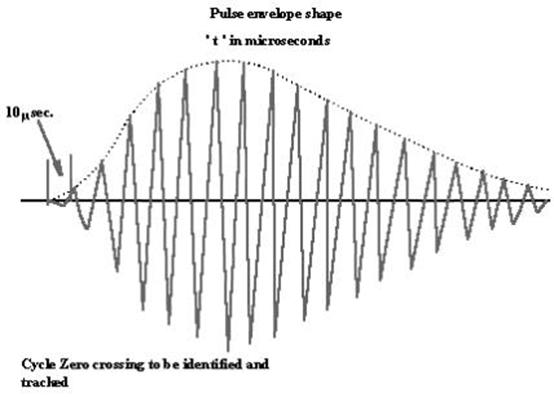
Zero Crossing: This diagram illustrates the third
cycle in the Loran pulse.
PHASE
CODING
To reduce the effects of interference and noise on
time difference measurements, and to assist in distinguishing between master
and secondary stations, the carrier phase of selected transmitted pulses is
reversed in a predetermined pattern.
The
pattern is shown below, where a minus sign indicates an inverted pulse
(180° phase shift), and a plus sign means no phase shift. This pattern
is repeated every two GRI’s.
Simply stated, phase coding determines whether the
first peak in the pulse is upwards or downwards.
Phase
Coding
TIME
DIFFERENCE MEASUREMENTS
The basic measurements made by Loran-C receivers are
to determine the difference in the time-of-arrival (Time Difference, TD)
between the master signal and the signals from each of the secondary stations
of a chain. Each TD value is measured to a precision of about 0.1 microseconds
(100 nanoseconds) or better. As a rule of thumb, 100 nanoseconds correspond to
about 30 metres. The principle of time difference measurements in hyperbolic
mode is as illustrated.
Time Difference Measurements
AUTOMATIC
OPERATION
Today’s state-of-the-art, solid-state Loran-C
transmitters are adapted for automatic operation.
The functions are monitored at the Control Centre,
which has the capability of initiating corrective action using data
communications.
Loran-C Receiver
Latitude/Longitude Corrections
Today’s Loran-C receivers are
equipped with microprocessors which are designed to internally compute the
latitude and longitude co-ordinates of the receiver, based on the Time
Difference (TD) readings, and directly display these values.
This may reduce the need to
possess Loran-C charts, though it is still required.
WHY?
The latitude/longitude
computation may be based upon a pure sea water path.
This leads to errors if the
Loran-C signals from the various stations involve appreciable overland paths
since the speed of the signal will decrease by varying amounts, depending on
the nature of the earth’s surface over which it is passing.
Loran-C operates by measuring
the difference in arrival times of the signals from the different stations in
the Loran-C chain, and thus any unforeseen variation in the speed of a signal
will result in an error in the latitude/longitude reading.
Note that when the receiver is
being used in the time difference mode (time difference readings being used to
manually plot lines of position on a Loran-C chart), these errors are minimal
and the system should be accurate to within ¼ nautical mile.
This is because the Loran-C lattice on a nautical
chart has already been adjusted to allow for the signal variation as it travels
over land.
It is therefore necessary that
before using the latitude/longitude feature of the receiver, to check the
manufacturer’s operating manual to determine if corrections are necessary and
how they may be applied to compensate for overland paths in order to obtain a
greater fix accuracy.
The correction can be applied in either of two forms:
insertion of a correction when the vessel is at a known location, or
the insertion of a correction factor that is determined from a table or chartlet.
The latter is called an
Additional Secondary Phase Factor (ASF) correction, and can be used to
ascertain the numeric value to apply. These corrections will normally be valid
only within 50 to 100 miles of the location at which the correction was
inserted because of the changing effects of landmass on the Loran signals in
the different areas.
PRECISION
CLOCKS
To achieve high positioning accuracy within the
service area, Loran-C transmitter stations are equipped with a bank of atomic
clocks, which provide the timing for the transmitted Loran-C signal.
Precise navigation with Loran-C demands that the error
in the timing system must not exceed a few tens of nanoseconds. For Northwest
European Loran-C System (NELS), it is specified that a station’s clock shall
not deviate by more than 30 nanoseconds from the clocks of the neighbouring
stations. Achieving this precision in timing it is necessary to continuously
measure the time deviation between the clocks in the system.
ADDITIONAL
SECONDARY FACTOR (ASF)
A Loran-C receiver computes distances from Loran-C
transmitting stations using the time of arrival measurements and the
propagation velocity of the radio ground wave to determine position.
Small variations in the velocity of propagation
between that over seawater and over different landmasses are known as the
Additional Secondary Factor, or ASF.
Corrections may be applied to compensate for this
variation. Such corrections may improve the absolute accuracy of the Loran-C
service in positions where the received Loran-C signal passes over anything but
seawater on its way from transmitter to receiver. The values of ASF depend
mainly on the conductivity of the earth’s surface along the signal paths.
Seawater has high conductivity, and the ASFs of
seawater are, by definition, zero. Dry soil, mountains or ice generally have
low conductivity and radio signals travel over them more slowly, giving rise to
substantial ASF delays and hence degradation of absolute accuracy.
Fortunately, ASFs vary little
with time, and it is possible to calibrate the Loran-C service by measuring ASF
values throughout the coverage area.
SERVICE
INTEGRITY
Loran-C stations are constantly monitored to detect
signal abnormalities, which would render the system unusable for navigation.
“Blink” is the prime means by which the user is
notified that the transmitted Loran-C signal does not comply with the system
specifications. Blink also indicates
that the Control Centre cannot ensure that the signal complies with these specifications,
for instance, as a result of discontinuation of data communications linking the
Control Centre to the stations. Blink
is a distinctive change in the group of eight Loran-C pulses that can be
recognized automatically by a receiver so the user is notified instantly that
the Loran-C chain blinking should not be used for navigation.
Blink starts at
a maximum of 60 seconds after detection of an abnormality. Automatic blink initiated within 10 seconds of a
timing abnormality may be added where Loran-C is extensively used for aviation
purposes.
ACCURACY
The Loran-C service will support an absolute accuracy
varying from 185 meters to 463 meters (0.1 to 0.25 nautical miles), depending
on where the observer is within the coverage area. Absolute accuracy defines a
user’s true geographic position (latitude and longitude). Repeatable accuracy
is a measure of an observer’s ability - by using a navigation system such as
Loran-C - to return to a position visited previously using the same navigation
system. Loran-C repeatable accuracy is sometimes as good as 18 meters and is
usually better than 100 meters within the coverage area.
FUTURE OF LORAN-C
Outside the
In 1997, an independent study was conducted in the
At the ICAO CNS/ATM implementation conference held in
The reason given was that the possibilities of
jamming, solar events, etc., were now better understood. Excellent though GPS
may be, its problem is that it is so low powered that the signal can easily be
blanked out or disrupted - as demonstrated at an 1997
The notion of GPS as sole means of navigation is dead.
Suitable backup systems cited are triple inertial, VOR/DME and LORAN-C.
As of September 1998, the American DoT
confirmed that the existing LORAN-C chains will be maintained and upgraded, at
least to 2008, “in the transition period to satellite based navigation”.
Loran’s wavelength and signal strength enable it to
penetrate into areas where GPS has difficulty because of line-of-sight blockage
as in urban or forested situations. Loran can even penetrate some buildings.
The most recent draft European Radio Navigation Plan
(ERNP) and European Commission report (