| Controls | Display | Errors | Antenna | Plotting |
RADAR
Principle
Essential
sections of a basic receiver and display
Antenna
drive unit; rotates the antenna at constant speed
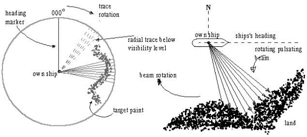
Heading
marker switch; closes when main beam is in line with ship’s head and
causes the PPI heading mark to appear
Bearing transmitter;
driven by the antenna which transmits electrically the antenna beam
bearing information
Electronic
switch (T/R cell): or the transmit/receive cell (T/R), switches at high
speed between transmit and receive modes: essentially a receiver protection
device
The receiver circuit of the Radar is an extremely
sensitive part of the receiver as it deals with signal voltages of an extremely
low value.
The voltages of the received echo signal may be as low
as a millionth part of a volt. The receiver must therefore amplify the signal
by anything between 1 and 10 million times, so as to produce adequate voltages
to be displayed onto the CRT.
The echo signals that are received have however the
same frequency as the transmitted pulse as well as the same shape (envelope) as
that which was imparted to the transmitted pulse by the modulator and pulse
forming circuit.
The weak echo signals; with the high frequency have
now to be amplified; however the amplification of signals with such high
frequencies is extremely difficult. As such the frequency (I.F.) that is
finally amplified is a much lower frequency (between 45-60MHz, depending on the
manufacturer) but the shape of the pulse remains the same.
How do we get the lower frequency – the Intermediate Frequency (I.F.)?
The process that is used is that, the incoming weak
signal is mixed with another signal of nearly the same frequency. This signal
is generated within the radar unit in the Local
Oscillator.
Thus the local
oscillator – single cavity resonant oscillator – generates a single
frequency, which is mixed in the mixer
circuit with the incoming weak echo signal. The frequency generated in the L.O. is very close to that generated by
the magnetron.
The frequency obtained from the local oscillator can
and is changed by two specific controls – one a coarse control and the other a
fine control.
The coarse control is control of the physical size of
the cavity – done by the manufacturer or at the time of installation by the
technician.
And the fine control is exercised by small variations
in the electronic conditions associated with the resonant cavity – done by the
radar operator – mariner.
Mixer; an
electronic circuit which converts the incoming echo signal at the transmission
frequency to a much lower value known as the intermediate frequency (IF); since
it is easier to process later.
9445 MHz – from the echo, same as the transmit
frequency
9505 MHz – from the Local Oscillator
= 60 MHz – Output of the mixer (IF) – this is
amplified.
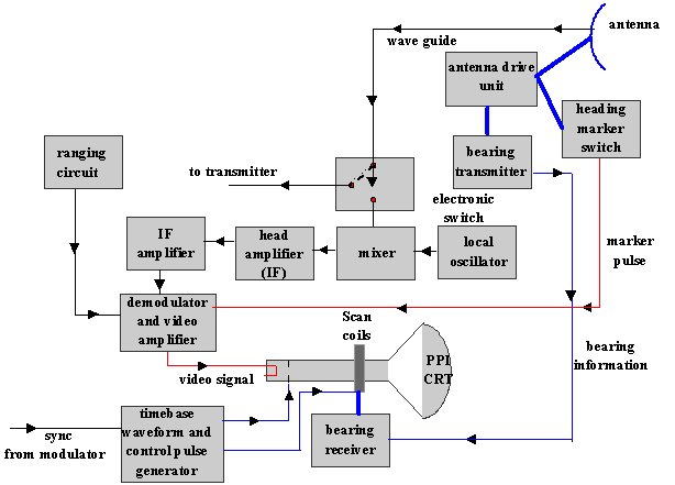
Local
oscillator; provides a frequency stable output signal having a value of
frequency either higher or lower than the transmission frequency by a value
equal to the IF.
Simultaneous application of the local oscillator
output and the echo signal to the mixer will produce a difference frequency,
which is the IF.
The IF signals contains the same information as the
incoming echo signal
Demodulator;
produces video pulses from the IF signal pulses
Video
amplifier; amplifies and processes the video pulses to a level adequate
to intensity modulate the PPI CRT beam current
Timebase waveform
and control waveform generator; generates the timebase
sawtooth sweep waveform and other rectangular waveform used to control the
display of targets during the sweep time only: the
circuits are synchronized to the transmitted pulse
Bearing
receiver: a small machine, which receives antenna-bearing information
and applies mechanical drive to rotating scan coils. The coils rotate in synchronism with the
antenna. There are also other methods of
producing a rotating scan at the PPI
Ranging
circuits; two separate circuits one of that produces periodic short
pulses to display accurately spaced concentric rings on the tube face (Range rings), the other circuit produces
a variable radius ring (variable range
marker) linked to an accurate range scale.
T/R cell (Transmit and Receive Cell)
The cell prevents magnetron high-level power from
entering the receiver arm and protects the sensitive receiver crystals from
damage when the transmitted pulse is present.
During periods of no transmission the cell allows the
received signal to reach the receiver crystals.
The cell is a chamber filled with inert gas. When the
magnetron fires, the gas very rapidly ionizes producing a switching action,
which directs the RF power to the antenna and away from the receiver.
At magnetron switch-off, the cell very rapidly
de-ionizes to allow received signals at short ranges to be processed by the
receiver.
The mixer
Receiver crystals are in fact semiconductor diodes
capable of rectifying radio frequency currents in the- Super Heterodyne
Frequency (SHF) band and are arranged in a mixer
circuit to operate in conjunction with the local oscillator.
The arrangement converts all incoming RF signals at
super-high frequency down to a much lower radio frequency known as the
intermediate frequency (IF) where the signal can be amplified and processed
using conventional RF circuit design.
The conversion is achieved by superb heterodyning the
received signals with a locally generated stable signal produced by a local
oscillator circuit.
A Gunn diode is the preferred choice of local
oscillator since it produces adequate output power,
operates at low voltage levels and has lower noise output than its predecessor,
the klystron.
The local oscillator is tuneable
over a range of a few megahertz by means of an electronic tuning control.
The head amplifier amplifies the target signals now
converted to the IF.
The effect of applying the target return signal is to
produce sum and difference frequencies at the mixer output.
For example, if Echo frequency = 9400 MHz and
The local oscillator equals 9460 MHz or 9340 MHz, as
the case may be.
Then the frequencies produced are 18 860 MHz or 18 740
MHz (being the sum values) together with 60 MHz, the difference frequency.
The sum and original frequency components are
de-coupled at the mixer output and the difference frequency is the desired IF.
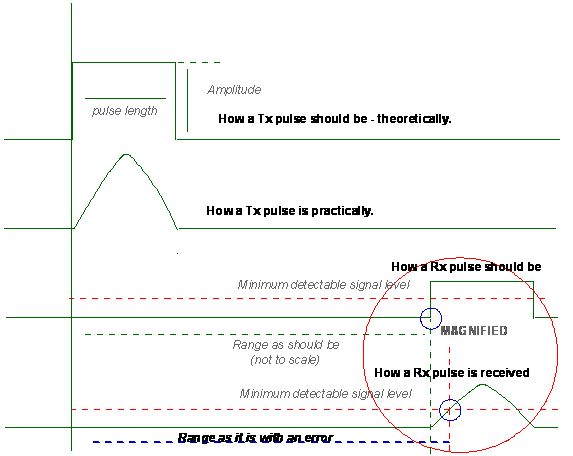
Raw echo signals converted to the IF will retain the
same pulse length as that of the transmitted and received SHF signal.
The IF amplifier
The purpose of the IF amplifier is to amplify the IF
signals produced by the mixer to a level sufficient to operate the video
detector (usually a few volts).
Pulse elongation
A facility
is provided to artificially lengthen the stored video signals by a fixed length
of time. The effect at the display is to
produce a more prominent paint of the digitized video.
Pulse stretching is usually made selective in that it
is only applied to pulses above a fixed duration usually on the 6-96 nm ranges
and only to displayed video beyond about 3 nm.
Echoes having duration less than that of the
transmitted pulse are rejected and not elongated.
Pulse Shape:
The Modulator unit includes a very fast operating
switch (electronic) which allows the discharge of the energy stored in the
Pulse Forming Network.
(Silicon controlled rectifier – like a diode, allows
current to flow only in one direction. The SCR however will allow current to
flow only if a trigger pulse is applied to a control electrode. When the
trigger pulse is present the opposition to current offered by the SCR drops
instantly to virtually zero. This produces a pulse of current having an
extremely fast rise time.)
The Pulse Forming Network stores the energy in
capacitors. Capacitors can store energy and when triggered discharge this
energy into a circuit but ordinary circuits have a long discharge time and
consequently the charge falls to low levels – thus this defeats the steady
charge that is required in a Radar circuit. This is overcome by a series of
capacitors and inductors.
Note that no signal is required to terminate the
discharge, whenever the energy is drained out the pulse is terminated.
The duration of the discharge and thus the pulse
length is therefore is a function of the amount of energy stored in the
capacitors.
The amount of energy stored again is determined as to
how many sections of the Network are put to use, this is determined by the
selection of the Pulse Length.
Thus it is seen that selection of the Pulse length will determine the amount of energy released by the system and therefore the amount of energy contained in a pulse and this will affect the ranging capabilities of a Radar.