| Controls | Display | Errors | Antenna | Plotting |
RADAR
Display
Relative
motion display (unstabilized)
Own-ship’s heading, indicated by the heading marker is
usually adjusted to point at 000º on a bearing scale surrounding the
indicator.
Bearings
of target echoes can be measured by means of an electronic bearing cursor which
is effectively a radial line passing through the scan origin and reaching the
edge of the screen.
Since the ‘top’ of the PPI is generally arranged to
display the heading mark, it represents 000º relative and the resultant displayed
information is known as ‘ship’s head up’ (SHU) presentation.
It is also known as an ‘unstabilized’ display since no
compass bearing information is fed into the display.
A relative motion display will show all targets moving
in their correct scaled speeds and directions in a manner similar to that,
which would be seen by an observer, situated at the antenna site.
Stabilized display
This type of presentation is also known as north up display.
In this the ‘top’ of the screen at 000 degrees is
represented as true north, achieved by feeding the ship’s heading from the
gyrocompass to the display.
As own-ship changes course the displayed heading mark
swings to the new course whilst other targets are shown on their correct scaled
relative courses referred to the top of the indicator.
In
this case if the own ship has a course of 180º then the heading line of
own-ship would point constantly to the bottom of the PPI.
For this reason RADAR’s today also provide a facility
for course up display; in this
case if own ship had a heading of 180º, the ships head would indicate 180º but
the heading marker would be on ‘top’.
Sea
Stabilized:
Whenever ARPA is used in the True track mode, data
relating to own vessel’s motion is fed in from the speed log and from the gyro/magnetic
compass.
Assuming that the speed log is feeding in the vessel’s
speed through the water and is not on
the ‘bottom lock’ mode, then the
displayed true track of the vessel would be sea stabilized.
Vectors would therefore indicate the true track through the water of other
vessel’s as well and thus would also the visual aspects of the other vessel’s,
irrespective of any tide/current experienced.
IT IS THEREFORE VERY IMPORTANT THAT WHEN ARPA IS USED
IN THE TRUE TRACK ANTI COLLISION MODE, THAT IT IS ONLY USED IN THE SEA
STABILIZED MODE.
The above
is the reason that in spite of a vessel being equipped with a GPS receiver, it
is compelled by regulation to carry an operational speed log. The ARPA
has to have a feed from the speed log.
Ground
Stabilized:
Coastline drift may be prevented by feeding in the set
and drift due to the current/tide, or by having the feed come in from the speed
log working on ‘ bottom lock’ condition. Or also by incorporating the CMG
obtained from the GPS.
Another way is to have the facility of ‘echo reference’ lock on to a stationary
target (selection of the same requires utmost care, and is not recommended for
the novice).
Under the above the display becomes ground stabilized.
The displayed vector will then indicate the targets true tracks. Of course due
to the potentially misleading effect of the data relating to the tracked
vessel’s aspect, this mode should not be used when assessing collision risk or
planning avoidance strategy.
Radar Plotting
There are advantages of using either a True or a
Relative motion display. Relative motion displays and subsequent plotting gives
an immediate indication of which ships are on a collision course.
On the other hand, whether a target is stationary or
moving can be usually distinguished more readily with a true motion display.
Generally any one of the displays may be used, however
with the inherent advantage for collision avoidance, relative motion maybe more
suitable for open sea condition for collision avoidance.
Now regarding whether to use Ground stabilization or
not.
Well ground stabilization display may and will give a
misleading idea about a target/ship in coastal areas, involving tidal currents.
GPS speed in general gives ground speed, and there
lies the necessity of having a speed log, which can give input to the Radar of
the set and drift experienced by own vessel.
In the following example the same is highlighted:
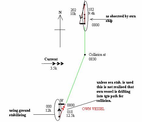
The
above is a case of an own vessel observing another target in an area where the
current is a factor. If ground stabilization is used, then the own vessel
course is taken by the ARPA as 000 deg. And speed of 12k, however due to the
current the actual vector of own vessel is
Thus unless sea stabilisation is used, the plot will
give a totally erroneous result and will seem that the vessels are passing
clear when actually they would be colliding.
This neccesitates the use of a speed log as is
mandatory under SOLAS
True motion display
Own-ship and targets can be displayed moving with true motion on the PPI, that is having
corrected scaled velocities by inclusion of a true motion unit to modify the presentation of target and ranging
information on the screen.
If the PPI scan origin is itself moved at own-ship’s
scaled velocity, all other moving targets will be displayed in real time moving
at their scaled velocities.
Fixed targets do not appear to move if one’s own
course and speed are relative to ground.
The arrangement provides a display which is chart-like in presentation
and from which plotting information is quickly obtained, usually in conjunction
with a reflection plotter.
A compass stabilized display is converted relatively
simply into true-motion mode by use of a set of orthogonal fixed deflection
coils. In some types of display these
may also serve as the sweep deflection coils.