| Controls | Display | Errors | Antenna | Plotting |
RADAR
Reflectors
Aids To
Radar Navigation
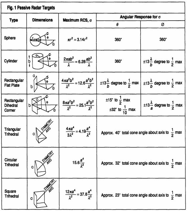
Trihedral reflector
Most radar reflectors are
variations on the 3-sided corner reflector, also known as a corner cube or a
trihedral reflector.
The principal echo from a
trihedral reflector will be strongest when its “pocket” is oriented directly
towards the radar.
As the trihedral reflector is
rotated off this axis in any direction, the echo becomes weaker, and drops by
half (-3 dB) at an angle of 12° to 20° from the axis of symmetry, depending on
its specific shape.
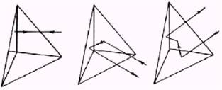
With increased rotation, the
return continues to drop to almost zero as one of the three sides
approaches an edge-on attitude to the radar.
When one edge is exactly
edge-on, there will be a strong but narrow return, caused by the other two
edges acting as a dihedral (2-sided) reflector, or one side acting alone as a
flat plate reflector.
These returns can be very
strong, but so narrow in angle as to have little value.
Octahedral Reflectors
The classic octahedral reflector
is made of three planar circles or squares of metal intersecting at right
angles, forming eight trihedral reflectors.
In
the usual “catch rain” position, one trihedral will face up and one down, and
the remaining six are arrayed around a circle, three oriented 18° above the equator,
and three 18° below.
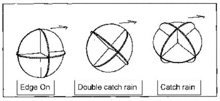
This optimizes the return from
the “pockets”, and avoids the nulls or gaps as best as is possible, but only at
a 0° angle of heel.
Considerations
of heel angle has led to the “double catch rain”
position (see figure), with one planar surface oriented vertically along the
vessel’s axis, and the other two planes ±45° from the vertical.
This is not the ideal with no heel angle, but moves towards the “catch rain” position
as the boat heels.
Radar navigation aids help
identify radar targets and increase echo signal strength from otherwise poor
radar targets.
Buoys are particularly poor
radar targets. Weak, fluctuating echoes received from these targets are easily
lost in the sea clutter.
To aid in the detection of these
targets, radar reflectors, designated corner reflectors, may be used.
These
reflectors may be mounted on the tops of buoys. Additionally, the body of the
buoy may be shaped as a reflector.
Each corner reflector, shown,
consists of three mutually perpendicular flat metal surfaces.
A radar wave striking any of the metal surfaces or
plates will be reflected back in the direction of its source. Maximum energy
will be reflected back to the antenna if the axis of the radar beam makes equal
angles with all the metal surfaces. Frequently, corner reflectors are assembled
in clusters to maximize the reflected signal.
Although radar reflectors are
used to obtain stronger echoes from radar targets, other means are required for
more positive identification of radar targets.
Radar beacons are transmitters
operating in the marine radar frequency band, which produce distinctive
indications on the Radar displays of ships within range of these beacons.
There are two general classes of
these beacons:
Racons, which provide both bearing and range information to the target, and
Ramarks which
provide bearing information only.
A racon
is a radar transponder which emits a characteristic signal when triggered by a
ship’s radar.
The signal may be emitted on the
same frequency as that of the triggering radar, in which case it is
superimposed on the ship’s radar display automatically.
(The signal may be emitted on a separate frequency, in which case to
receive the signal the ship’s radar receiver must be tuned to the beacon
frequency, or a special receiver must be used.)
In either case, the PPI will be
blank except for the beacon signal.
However, the only racons in service are “in band” beacons which transmit in
one of the marine radar bands, usually more often in the 3centimetre band though
the 10 centimetre ones are also in use.
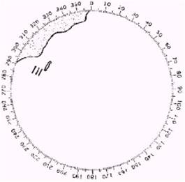
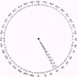
The racon
signal appears on the PPI as a radial line originating at a point just beyond
the position of the radar beacon, or as a Morse code signal displayed radially from just beyond the beacon.
A ramark
is a radar beacon which transmits either continuously or at intervals. The
latter (Racon) method of transmission is used so that
the PPI can be inspected without any clutter introduced by the ramark signal on the display.
The ramark
signal as it appears on the PPI is a radial line from the center.
The radial line may be a
continuous narrow line, a broken line, a series of dots, or a series of dots
and dashes.
Radar beacons (Racon);
A receiver-transmitter device
associated with a fixed navigational mark which, when triggered by a radar,
automatically returns a distinctive signal which can appear on the display of
the triggering radar, providing range, bearing and identification information.
Transponder
A receiver- transmitter device
in the maritime radio navigation service which transmits automatically when it
receives the proper interrogation, or when a transmission is initiated by a
local command. The transmission may
include a coded identification signal and/or data. The response may be displayed on a radar PPI, or on a display separate from any radar, or
both, depending upon the application and content of the signal.
Transponder is a device which
when properly interrogated can provide for – ship target identification and
echo enhancement with the proviso that such enhancer should not significantly
exceed that which could be achieved by passive means on the radar PPI of an
interrogating ship or shore station;
Transponder are used to meet the
following operational requirements
identification of certain classes of ships (ship-to-ship)
identification of ships for the purposes of shore surveillance.
search and rescue operations.
identification of individual ships and data transfer.
establishing positions for hydrographical purposes.
In making a landfall and in harbour approaches a problem of navigation is the
identification of lighthouses and lightships marking either hazards or
approaches to buoys channels. In
conditions of poor visibility many vessels may congregate in harbour approaches, and positive identification of a single
known mark - light vessel or buoy may enable a channel to be identified among
many ship echoes.
A racon
is required to transmit a signal, the “response” each time it receives a pulse
from the radar set which may have any frequency within the 200 mHz wide band.
The response of the in-band racon must be of a frequency that can be received and
processed by th same radar.
The Racon
may receive the radar pulse via a broad band emitter covering the full 200 mHz in order that it may be picked
by the radar receiver, tuned to a particular frequency within the band.
The usual method is to alter the
frequency of the response a function of time and repeat this periodically in a
saw-tooth fashion.
As a result the radar will pick
up the response only at those moments that the transmitted frequency is within
the bandwidth the radar received; at other moments the response will not
received.
A slow sweep in-band Racon, the frequency sweep takes place at slow rate (2-4 mHz) and the process is
consequently repeated long intervals of time (50 - 100 s).
In that case the response is not
received at every sweep of the radar beam over the Racon;
fact the period that no information is received may be too long for
navigational purposes.
This disadvantage is overcome in
a fast sweep Racon where the frequency of the
response is altered very fast, so that it sweeps through 200 mHz in 5 - 7 microsec.
The problem does not present
itself with Fixed Frequency Racon,as
the response is always transmitted at the same frequency and is picked up by a
special receiver at the radar.
The slow sweep in-band Racon response can consist of a single pulse, usually of
some 45 microsecond duration for every radar pulse received.
The radar pulses recur at the
rate of the PRF and the triggered responses which integrate to provide a radial
paint on the PPI beyond the target, 3.6 n. miles long for a 45 micros response.
This paint starts at a short
distance from the target which is determined by the overall system delay of the
Racon.
The indication on the PPI is a
flash towards the edge of the screen the bearing of the beacon and at a range
some 300 metres great than the true range of the Racon.
The response may be coded to
consist of a number of consecutive pulses of predetermined duration, thus
providing a characteristic paint on the PPI for the purpose of identification.
Most radar sets are equipped
with a differentiator circuit for the purpose of suppressing rain clutter.
The differentiator reacts up
sudden alterations of the incoming signals and accentuates the suppressing
constant echoes with a slow rise time.
The pulse of slow sweep Racon lasts at least
several microseconds even when coded and it is purposely given slow rise
time. Its
characteristics therefore resembles those of rain echoes and can be
suppressed by actuating the differentiator.
This is of advantage when interference is caused by side lobe triggering
at short range, as the interference can be removed at will by means of the differentiator.
Obviously, if a slow sweep
in-band Racon is hidden in rain echoes, the
differentiator may remove both the rain and the Racon
from the screen.
IALA recognises
a requirement for 3 types of Racon
Long range Racon,
for the purpose of enhancing the echo of and identifying a landfall mark at a
maximum range of 25 n.miles.
This Racon would use a sweep
duration of 90- 120 seconds. The Racon antenna can have a narrow vertical angle of
divergence and so constructed as to have a high gain in the approach sector.
Medium range Racon,
for the coastal navigation and identification of navigation marks at ranges of
8 to 15 n. miles. The sweep duration
should be 60 -90 seconds.
Short
range Racon, for ranges up to 6 n. miles and for use
in inshore waters.
A faster sweep rate if necessary
in order to provide more frequent information and a sweep duration of 60
seconds or less is recommended.
This equipment, often destined
for buoys, must have a wide vertical angle of divergence and therefore be
fitted with a low gain antenna.
Marine Racon
utilised a coding unit which can give a choice of
eight three digit morse
signals. i.e. the letters G.R.O.W.D.U.S.K. followed by
a normal racon flash towards the edge of the
screen. When two Racons
are sited so close to each other that each triggers its neighbour,
a virtual continuous transmission will be the result. This is a situation that should be avoided.
If a radar
equipment and a Racon are installed in close
proximity to each other such as may be the case in a lightvessel,
mutual. interference and possible damage to the
equipment may be expected when they operate at the same time. This may be overcome by the application and
complicated equipment.
When a Racon
is mounted on a buoy, its position should be monitored; shipping must be warned
and the Racon emission switched off by remote control
if the buoy is known to be off station.
RAMARK
PRINCIPLES OF OPERATION
A RAMARK is a beacon that
provides bearing information only.
It comprises an unsychronized transmitter of which the frequency is swept
over the marine band so that its transmission can be received and displayed by
any commercial radar set operating in the band for which the beacon is
designated (X-band or S-band).
Consequently it is an in-band
beacon.
Whenever the emitted frequency
is within the radar receiver bandwidth the radar will pick up and display the
signal each time the antenna is directed at the RAMARK.
In this way a duty cycle can be
introduced whereby periodic information is provided at longer or shorter
intervals depending on the sweep rate and the receiver bandwidth, as in the
case of slow-sweep in-band Racon. The transmission
may be coded by pulse or by frequency modulation in order to provide
identification; this appears on the PPI as a succession of dots or dashes.
The possibilities of coding are
thus very limited.
POWER, RANGE AND INTERFERENCE :
Interference can be caused by a Ramark at close range when its emission is picked up by the
side lobes of the radar antenna. This results in a wide sector of paint on the PPI which can
in an extreme case cover the entire screen and obliterate all echoes.
This interference is much more
severe than that experienced with Racon, the latter
being confined to ranges greater than that of the target and being limited by
the length of the response. A long
duration Ramark duty cycle, either obtained through a
slow sweep rate or by intermittent, transmissions may be employed to ensure
that there is a minimum acceptable period of time that the PPI is clean. With a slow sweep rate long pulses may be
used in which case, the interference may be removed by the differentiator.
However, at moments that Ramark information is needed the differentiator must be
switched off, and the interference then experienced will persist and spoil the
radar picture for some time after the differentiator is switched on again,
because of the afterglow properties of the radar screen.
The Ramark
signal on the PPI originates from the ship’s own position on the screen. When within range of several such beacons
this position becomes the hub of a number of spokes and this makes the picture
very crowded in the area close to the vessel which is so crucial for its
safety. Because Ramark
suffers from some serious disadvantages and only provides bearing information
its application has been limited.
Swept frequency radar beacon
A radar beacon in the maritime
service which is capable of transmitting a warning signal, automatically, to
any radar-equipped ship in its vicinity - the beacon will be triggered
automatically by the transmissions of any radar operating in the appropriate
radar band the return signal is to be displayed on the PPI of the triggering
radar.
Swept frequency radar beacons
are used only for the following purposes; it should not be used to enhance the
detection of marine craft.
Ranging
on and identification of positions on inconspicuous coastlines.
Identification
of position on coastlines which permit good ranging but are featureless.
Identification of selected
navigational marks both seaborne and land based.
Landfall
identification. as a
warning to identify temporary navigational hazards and to mark new and
uncharted dangers.
Fixed frequency radar beacon :
A radar beacon in the
maritime radio navigation service which is capable of responding automatically
to any radar-equipped ship in its vicinity, and which returns a signal on a
fixed frequency which can be displayed on the PPI of a suitably configured
radar - the beacon will be triggered automatically by the transmission of any
radar operating in the radar band, the signal may be displayed continuously,
either separately or super-imposed on the radar picture, or may be switched
off, at the option of the operator.