| Sailings | Chart Work Exercises | Information from Charts | Tides | Sextant |
Terrestrial Navigation
Information from Charts
The
Chart Catalogue
Many countries publish Chart Catalogues.
Among the principal chart publishers is the Hydrographer
to the Navy (U.K.). However other countries that do publish charts also make
available data to the International Hydrographic Organisation, who allows
different countries to publish these charts. Thus the 2nd publishers just print from whatever data they get from the
IHO and the survey is conducted by the 1st country. These series are
termed International series and bear the stamp of the IHO.
To give an example note
the label on the following:
Here you see the surveying country as
The charts that are published anywhere follow
the rules as laid down by the IHO, thus learning to use a chart of one country
makes one proficient in using other charts.
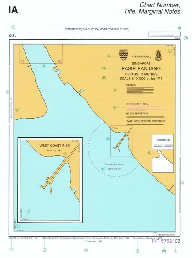
The above picture is self explanatory if
read in conjunction with the following picture:
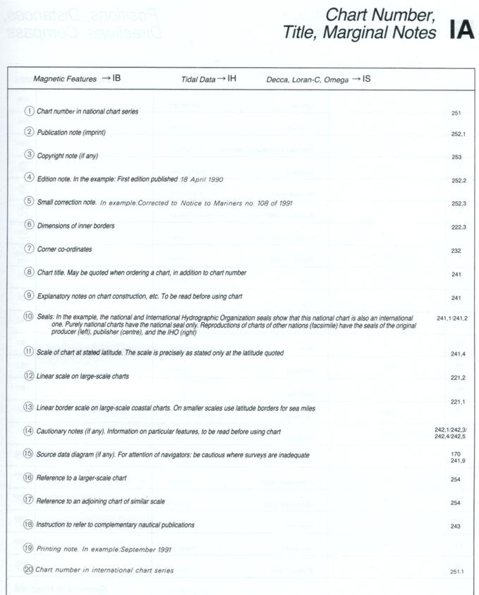
Prior taking a new chart for use the
following must be checked:
- The
correction record at the bottom – left hand corner
- The
year of publishing
- The
scale of the chart, and
- The
source table
The source table would give the type of
survey that was carried out and when. Many charts are published with some areas
being surveyed recently while in other areas the data is taken from previous
surveys (which may be quite old).
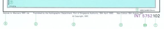
All International series charts have the
International number beside the national number of the chart.
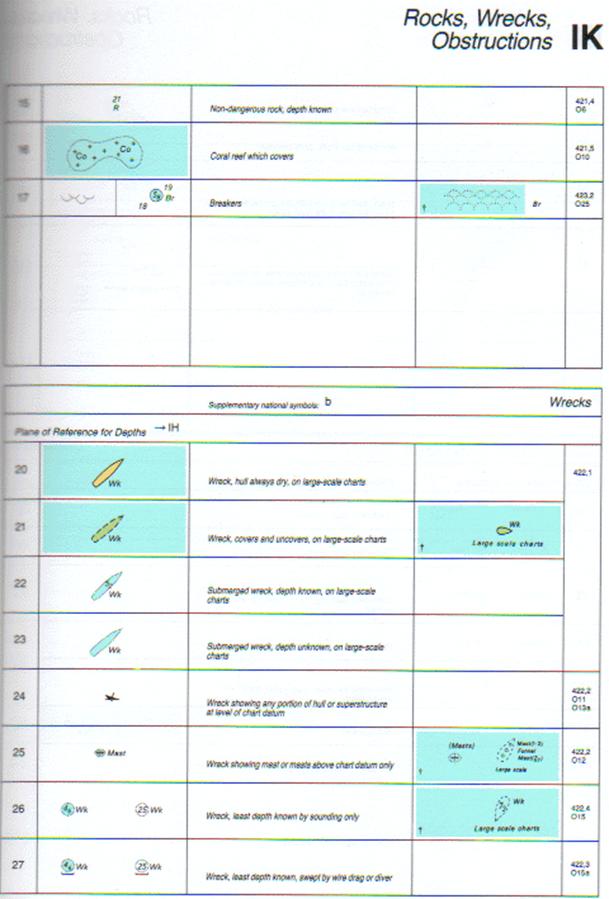
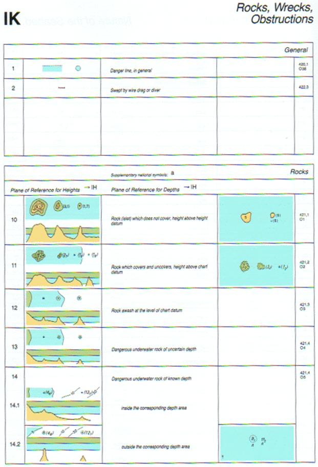
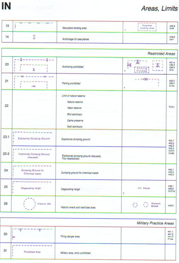
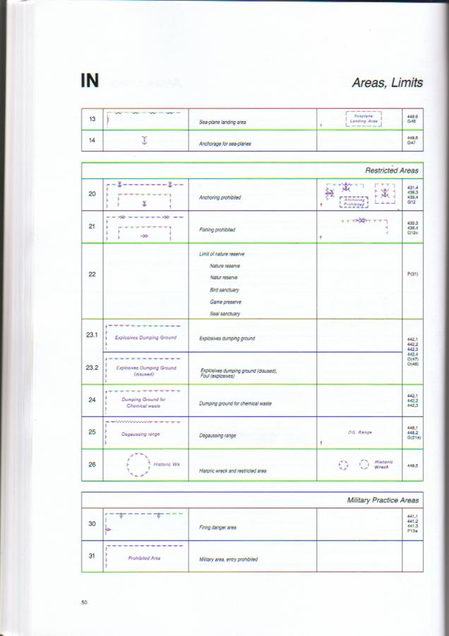
Learning
the symbols printed on the Charts:
While charts are published, the
abbreviations, the symbols and the colour code is not
mentioned on the charts and the mariner is expected to know of such things
prior to using the charts.
The above symbols and the abbreviations
are printed in another publication called Chart 5011 by the UK Hydrographic
office. Other countries do have such books.
To give an example of a few items:
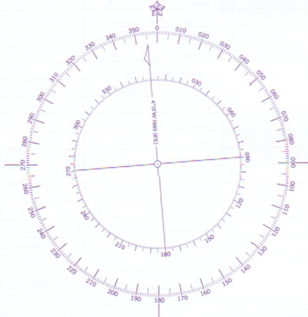
The above shows a compass rose. The circle
is always projected in the above manner, the top of the rose pointing to the
top of the chart.
The outer ring is the one from where the
true bearings are plotted.
Within the outer ring there is an inner
ring graduated in the same way but slightly off with reference with the outer
ring. This inner ring is the one that has not been compensated with the
variation.
Thus if the bearings that are plotted are
corrected only for deviation then these may be drawn using this ring
graduation.
The variation is again written on the
north marking line – in this case is written as:
4°15’ W 1985 (6°E)
Meaning that in 1985 the variation at that
place, where the rose is printed was 4°15’West and that
the yearly change is 6°E. Now to get the variation for 2004, we have to
multiply the number of years since 1985 – 19 years with 6°
and get 114°. So 1°54’ have to be
subtracted from 4°15’W. Subtract since the change was E.
Passage Planning
Passage Planning is a way of minimising
the risk of navigational error. In areas
of high traffic density and restricted available water, the requirement for
pre-planning becomes even more necessary.
The aim of passage planning is to prepare for the
navigation of the ship so that the intended passage can be executed in a safe
manner in respect of both the vessels and the protection of the environment, by
ensuring the proper and positive control of the ship at all times. Without such planning, the time to process
essential information may not be available at critical times when the bridge
team is occupied in confirming a landmark, altering course, avoiding or
monitoring traffic and carrying out other bridge duties, such as external
communications and internal communications within the ship. Under these circumstances, unless there is an
effective plan in place, mistakes and errors may go undetected leading to
disastrous consequences.
The construction of an effective passage plan
encourages all those concerned to foresee potential problems and plan a
strategy to minimise the risk.
No specific courses are laid down as it is necessary
for all vessels to plan, and lay down on the chart, their own course.
Where alterations of course are required, the latitude
or longitude or approximate bearing to a navigational mark, which ever is more
appropriate, is used singly to indicate an obvious change of direction in the
traffic separation scheme. This to
ensure that navigators are not using a set of advised, fixed positions thus
avoiding vessels using exactly the same courses in their individually developed
plans.
Checklists
The Checklists are a basis for individual ships either
amending or drawing up their own checklists.
They should not be considered to be definitive but the basis for
individual ships to expand upon. The
checklists incorporate checks for readiness for transit and reporting.
Parallel
Indexing
This is the simplest and quickest pilotage
technique that gives continuous monitoring of the track that the ship is making
good. Parallel indexes should be used,
whenever practicable, while transiting through coastal areas. To this end, for every leg, suggested
reference points should be included into the Passage Notes. These points are known to be radar
conspicuous and likely to be available at all times. Buoys, especially buoys known to be prone to
damage or movement, should never be used.
Wheel Over Positions
Course alteration positions should be chosen to allow
for proper monitoring during ship turns.
Ships using a plan would have their maneuvering characteristics and the
ships data must thus be consulted when planning a wheel over position.
Where possible, techniques for monitoring the turn
should be used. This may be using a rate
of turn indicator, parallel indexing or other suitable techniques.
Emergency /
Contingency Plans
By preparing in advance for possible contingencies, a
quick and effective response can be made when the unexpected happens. Plans should be considered for coping with,
amongst others, steering failure, power loss, loss of propulsion or any other
type of accident or emergency that may occur on a ship that will affect the
navigational ability.
To this end, the Passage Notes, for each leg, should
indicate the available depth of water.
PASSAGE
PLANNING NOTES
The requirement for an effective plan is included in
the STCW Convention that states - "The
intended voyage shall be planned in
advance taking into consideration all pertinent information and any course laid down should be checked before
the voyage commences."
Purpose
The purpose of passage planning is to ensure control
over the safe navigation of the ship at all times. This is normally achieved by entering onto
the chart as much information as is available to enable immediate reference
should the unexpected occur. Also to monitor the progress of the vessel along the intended
tracks and within previously planned and agreed parameters.
Information
Required to Formulate a Passage Plan
Prior to compiling a passage plan as a minimum, the
following publications will be required in addition to this guide:
chart catalogue
corrected
navigational charts
routeing and pilot
charts
IMO Ship's Routeing
sailing directions
and pilot books
light lists
tide tables
tidal stream
information
Navtex local
warnings and Notices to Mariners (Navareas, Hydropacs) radio signal information (including VTS and
pilot service) owner's and other unpublished sources
manoeuvring data
Mariner's Handbook
climatic
information and weather forecasts electronic navigational systems information
(as applicable) personal experience of ships navigating officers.
Additionally, when compiling the passage plan the
availability and reliability of the following have to be considered at the
early part of the planning phase:
main propulsion
system
steering gear
navigational equipment
anchors
thrusters (if
equipped)
auxiliaries
trim and
draught of vessel
transverse stability
the availability
of manpower.
Preparing
the plan
When preparing the plan the
navigating officer will need to take account of the following:
a.
Adequate under keel clearance at all times, including
allowances for squat, pitch, roll, swell, predicted tidal height and possible
increase of draught due to heel and trim
b.
safe distances off dangers, allowing for weather,
tidal stream, anticipated traffic, availability of safe water and navigational
systems in use
c.
alter-course positions which can be monitored
conveniently either visually or by radar
d.
management of chart changes, which should not occur at
critical points of the passage
e.
The Traffic Separation Schemes, and the requirements
of Rule 10
f.
predicted tidal stream information, leading to the
pre-working of allowances for set
g.
visibility of lights (especially in the Malacca
Straits), rising/dipping distances, arcs and colours of light sectors
h.
envisaged safe speeds along the route, taking into
consideration recommended area of reduced speed, leading to a speed plan for the
transit, and an ETA plan at the pilot station or
i.
storing position,
making due allowance for possible reduced visibility. A plan for reducing speed
under control should be considered
j.
selection of depths for comparison with the echosounder, taking note of the predicted height of tide
may be desirable for certain routes
k.
reporting points,
VHF frequencies, VTS requirements, areas of special concern and pilot station
frequencies if either requiring a pilot or areas of increased traffic density.
l.
abort positions for specific sections and contingency
plans in case of accident or emergency or bad visibility
m.
the primary and secondary systems of navigation to be
used
n.
requirements of any electronic chart systems
o.
all charts and publications available are up to date
p.
equipment status
q.
margins of allowable error, safety clearing bearings
and ranges
r.
the making up
of a bridge, or conning, notebook.
The master must satisfy himself that the passage plan
meets all his requirements and he must then ensure that all watch-keeping officers
are properly briefed; and that the plan is kept amended and upto-date for the
intended passage.
Passage
planning therefore should be a preparation for effective piloting by selecting,
and marking in advance,
those relevant navigational techniques which will lead to safe control of the ship and adherence to the plan.
Parallel
Indexing
As mentioned previously this is the simplest and
quickest pilotage technique, and is highly
recommended as it gives continuous monitoring of the track that the ship is
making good As with all radar techniques, parallel indexing should be practised in clear weather during straightforward passages
so that personnel become thoroughly familiar with the technique before
attempting to use it in confined or difficult passages, at night or in
restricted visibility. Great care should
be taken in identifying and confirming reference points on the chart and on the
radar; and also in verifying the radar range when using the parallel index.
Preparing
the Chart
1 .The first
step when preparing a passage plan is to identify and mark the 'no-go' areas on
the chart.
The charts supplied to ships are the same for
everyone, whether for use on board a VLCC at 25 metres draught or on a coaster
sailing at 3 metres draught. It is
therefore imperative that the chart is made suitable for the specific condition
of your vessel. This should be done by
marking the 'limiting danger lines' - often referred to as marking out the
'no-go areas.'
These are valuable safety limits to any plan for a
coastal. Lines must be drawn on the
chart to highlight where the vessel cannot go.
Proper allowance must be made for maximum draft and predicted tidal
height and any other limiting condition.
The concept of marking no-go areas has the following benefits:
a.
it forces consideration of the factors affecting under
keel clearance, which is always the high risk element
b.
it forces a
concentrated study of the chart, rather than just a glance it immediately highlights to anyone who looks at the chart the,
often large, areas that must be avoided.
It is not enough to depend on, say, printed depth
contour lines. The lines have to be
prominent in order to highlight the immediate danger quickly and effectively at
any time under any light condition.
It is important to draw the no-go boundaries as
accurately as possible. They should
show, for example, that the vessel can pass the wrong side of a mark, in an
emergency, although this may not normally be desirable. It can be seen from the study of some recent
incidents that had this information been immediately available, then a grounding or collision would most probably not have
occurred. In this context passing the
wrong side of a buoy is nothing compared with the consequences of even a minor
incident.
Insert the 'limits of safety'. Normally this will be an area either side of
the vessels intended track that may be acceptable to deviate within, under
normal circumstances. In the approaches
to ports as well as in some areas, however, this may be the traffic lanes
already on the chart. However in certain
areas, additional lines should be marked on the chart to highlight where it has
been considered that it is only safe to navigate under normal circumstances.
After these considerations have been made the vessels
intended track should be inserted.
The wheel over positions should then be marked on the
chart. When marking the wheel over
positions consideration should be given to the amount of rudder that will be
applied, the expected speed of the ship at the alteration position and also the
depth of water due to the effect on the turning circle of shallow water,
It is often valuable to insert the speed that is to be
maintained along certain sections of a leg.
This is especially true if an accurate ETA is required at a certain
point, e.g. for picking up pilots or rendezvousing for stores.
The methods to be used for fixing the vessels position
on different parts of the intended track should be entered onto the chart. The prime method should be by visual fix,
whenever possible, backed by radar or electronic means. If, from experience, it is known that there
are conspicuous landmarks or points for position fixing it is often worthwhile
to identify these.
The timing of fixing the vessels position should be
considered when passing though the congested waters. The requirement for fixing the vessels
position will vary considerably, based on the nearness of the most imminent
danger and also while executing and completing a turn. As a back up to frequent fixing, the use of
parallel indexing techniques will assist in ensuring the vessel is maintaining
the intended track and should be considered, especially in the more constricted
parts.
From experience it will become evident what
identifiable marks are radar conspicuous. It is of value to mark these radar
conspicuous targets on the chart for future reference. Weaker targets that may be usefully used in
clear weather may disappear in heavy rain and thus may not be available.
Clearing bearings for hazards, and to assist in
maintaining the track should be inserted onto the chart. These give a very quick method of checking
that the vessel is, at least, missing dangerous or noteworthy points.
Clearing ranges are another technique used by some
vessels to ensure that a minimum and maximum distance is maintained from a identifiable mark.
These should be considered on all vessels where parallel indexing is not
being employed and may especially beneficial when completing a turn.
Prior to entering a restricted section abort points
should be entered on the chart. At this
point it must be agreed that to proceed any further all systems etc. have to be
fully operational and the vessel is in readiness to proceed. As well as entering the abort point on the
chart it is often recommended that the action to be taken to abort is also
entered onto the chart. E.g. When reaching the abort point the engine speed is reduced
and the direction of turn, with possibly the helm order, entered so that all
personnel involved in navigating the vessel are fully aware of the agreed
action to be taken.
In addition to the abort positions contingency
planning should also take place whilst compiling the passage plan. By marking the "no-go areas" on the
chart, as suggested above, it should be readily apparent if there is sufficient
water outside the traffic lanes in which to anchor. By preparing in advance for possible
contingencies, a quick and effective response can be made when the unexpected
happens. Plans should be considered for
coping with, amongst other things, main engine failure, steering loss, port or
channel closures, radar failure, reduction in visibility, heavy traffic at
crucial points, movement or closure of a pilot station, or any of the accidents
and emergencies that can occur to a ship on passage.
The tidal streams and heights at the time of expected
transit should be marked on the chart.
The depth of water, in general, at sea should not pose a problem for
vessels, but if the height of tide is marked on the chart, in coastal waters it
will assist in contingency planning. The
direction and strength of the tide and current in certain parts,
can be very strong and should be marked on the chart in prominent
positions. This will assist, not only,
in predicting and understanding the movement of your own ship but also the
movement of others, especially slow moving vessels and tugs with tows.
In addition to the above it is suggested that the
reporting points are clearly marked on the chart, in addition to the positions
where it is necessary to change VHF channels.
Also the position of expected high traffic density
should be marked on the chart along with any other relevant information.
Monitoring
the Passage Plan
It is common practice to fix the ship's position and
then make an allowance for set and drift depending upon offset from the
previous fix. This approach to
navigation is REACTIVE, being based upon past observations. If either of these is wrong, then any
predictions using them will be erroneous.
When using fixes in this way, it is usually better to make the fixes at
regular and appropriately frequent intervals.
This enables a simple check to be made with respect to speed. It also helps the quick and effective
calculation of short-term EPs (Estimated Positions), using the latest course
and speed made good, to warn of any immediate problems developing.
However, in narrow and restricted waters, techniques
need to be used which enable the navigator to maintain a forward outlook, that is to be PROACTIVE, whilst monitoring the
deviation from the intended track being made good. Frequent, hurried visits to the chart table
to fix the vessel's position may not be the most effective use of the time
available. Also, whilst doing this the
overall sense of awareness can be interrupted and it is easy, during critical
phases, to become disorientated.
It is worth remembering to monitor the
echo-sounder. This instrument can often
provide the first warning signs that the vessel is standing into danger, since
in almost all situations the nearest land is beneath the vessel.
PASSAGE PLANNING
CHECKLIST
Charts
Are the charts the largest scale available?
Are they corrected for the latest Notice to Mariners and local navigational warnings?
Do the charts completely cover the area?
Sailing
Directions
Is the planned track following recommended routes?
Is the plan
following local regulations?
Are all potential hazards known?
Port /
Storing Information
Are local conditions known?
Is berthing / storing information available?
Tidal
Atlas/Tables
Have the stream strength and directions been discussed?
Have the tidal heights been discussed?
List of
Radio Signals
Where is the pilot boarding area?
Are
Where are the required calling
in points?
Weather
Reports
Is the local forecast available?
Local Agent
Has the agent advised of berth and berthing/stores and
storing requirements?
Vessel
Condition Comments
What is the draft and air draft?
What is the minimum acceptable underkeel
clearance?
Manoeuvring
Data
Have considerations for squat been made and are tables
available?
Chart
Information
No-go areas
Margins of safety plotted
Plotted tracks
Have we calculated the wheel-over points and what are
they?
Parallel index references
Required speed at differing way points
Tidal stream anticipated
Crew call out position
Tug meeting area
Abort positions
Contingency plans available?
Briefing
Were all navigators present?
Have the fixing intervals been determined?
Have fixing points been determined?
Have the primary navigation aids been determined?
Have the secondary means been discussed?
Have the areas of high risk been determined and
discussed?
Has the bridge team discussed the information flow and
has it been agreed?
Has the charted plan been discussed?
Has the watch condition been determined?
Have duties been assigned and understood?
Have the conditions for increasing the watch been
determined?
Have team members been made aware of any defective
equipment?
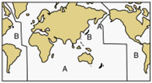
Buoyage
International Association of Marine Aids to Navigation
and Lighthouse Authorities (IALA)
The IALA buoyage system is
split into 2 regions A and B. Region B is mostly areas of the world with
American influence, Region A is mostly countries with
IALA Buoyage System ‘A’ and ‘B’
Visibility
of Lights:
Lights are placed on Light Houses at a
height of the light houses, depending on the intensity of the lights
themselves, the lights are marked as visible up to a distance of a certain
limit, the height of the observer when declaring the above is taken to be 15
feet (4.5 metres).
However the visibility of the lights at
the marked limit may be exceeded due to the height of the ship also.
The expression for obtaining the raising
of the light limit is given by:
Heights in feet:
Distance = (√Height of observer x
1.15) + (√Height
of Object x 1.15)
Heights in metres:
Distance = (√Height of observer x
2.083) + (√Height
of Object x 2.083)
Or
Distance = (√Height of observer x 2.1) + (√Height of Object x 2.1)
Example:
Assume the following:
Height of eye (Bridge): 21 m
Height of Light House (from List of
Lights): 60 m Range: 20 NM
Then the above equation would be as
follows:
Distance = (√Height of observer x
2.1) + (√Height
of Object x 2.1)
Distance = (√21 x 2.1) + (√60 x 2.1)
Distance = (4.58 x 2.1) + (7.75 x 2.1)
Distance = 25.9 NM
That is the light would be seen from a
distance of 26 NM.