| Sailings | Chart Work Exercises | Information from Charts | Tides | Sextant |
Terrestrial Navigation
Sextant
J
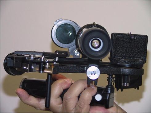
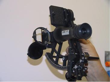
MARINE SEXTANT
A is the
Index Bar, which is free to rotate on a central axis under the mirror B.
C is a spring loaded clamp screw to keep the index arm
in firm contact with the arc as required.
D is the Tangent or slow motion screw, which only
comes into operation when the clamp is tightened. This screw when turned enables the observer
to measure angles more deliberately and accurately than would be possible by
simply sliding the Index arm across the arc.
G is the
Telescope, screwed into a Collar H, which can be raised or lowered by means of
the Screw I
B is a
mirror called the index glass.
The index glass is mounted on the round base plate
with its centre exactly over the central axis of the index bar and turns with
the index bar when it slides along the arc.
K is a screw
for adjusting the index glass to make it exactly perpendicular to the plane of
the sextant. It is called the First
Adjustment Screw.
L indicates four coloured shades of lighter and darker
hues to darken the image of the sun in the index glass.
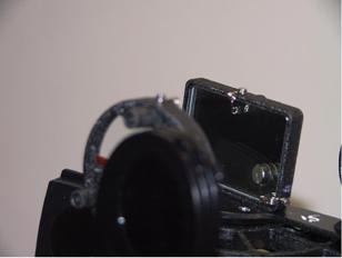
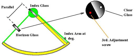
M is a glass, half of which is mirrored the other half
being clear glass, called the Horizon glass.
O is a small screw to adjust the horizon glass to make
it exactly perpendicular to the plane of the sextant. It is called the Second
Adjustment Screw. This screw is away from the plane of the sextant.
P is another screw to adjust the horizon glass to make
it exactly parallel to the index glass with the arm set at zero on the scale.
It is called the Third Adjustment Screw. This screw is next the plane of
the sextant.
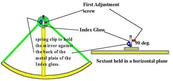
An adjusting screw is just a pinching screw, which
pushes the edge of the mirror forward when it is tightened up. It will be noticed that each of the three
adjusting screws there is a spring clip, particularly noticeable at the index
glass K. This spring clip presses the mirror back against the point of the
adjusting screw thus keeping the mirror in its proper position in the frame.
The optical part of the sextant consists of the index
glass, horizon glass, telescope and microscope.
It is known as an instrument of double reflection, because the rays of
light from the body under observation travel in the direction of the dotted
lines drawn in the SKETCH.
The original rays enter the index glass at a particular
angle, are reflected from it at the same angle of obliquity, and then pass into
the horizon glass. They are then
re-reflected from the horizon mirror and leave it at the same angle at which
they entered it, and this second reflected ray pastes through the telescope to
the eye of the observer at G.
The sextant is an instrument for measuring angles, its
name being derived from the extent of its limb, which are
not less than 60º (the sixth part of a circle).
The "limb” is the plain curved part of the instrument
in -which the arc is firmly embedded.
Being of double reflection, the arc is divided into
twice the number of degrees, which it actually contains, and angles up to 120º
can be measured and read off from an arc of 60º.
The arc is graduated to more than 120º at one end and
a little beyond 0 at the other end.
A sextant measures angles in any plane, vertical,
horizontal or oblique.
Vertical Angles: Altitudes of heavenly bodies that are
necessary for working many problems in navigation are vertical angles, also
angular heights of lighthouses and other fixed objects for finding distances
off shore. An angle subtended by the
height of a fixed object ashore (the value being calculated beforehand), and
which is used to enable a ship to maintain a certain distance from a hidden
danger, is called a vertical danger angle. An angle subtended by the height of
a ship's mast, which may be used for finding the distance from her - is also a
vertical angle.
Horizontal Angles: Angles measured between lights or
other fixed objects on the shore, and which are used for fixing the ship's
position by means of a station pointer, are horizontal angles, as are also
those measured horizontally for finding the ship's position without using a
station pointer. Horizontal angles
calculated or found out beforehand, and which are used for maintaining a safe
distance when rounding a hidden danger, are called horizontal danger angles.
With an ordinary sextant the limit is about 120º. A greater angle than that is impracticable on
account of the relation between the index and horizon glasses.
Since the sextant is an instrument of double
reflection, the angles measured by it being double the angle between the
reflecting mirrors. As the index mirror
is fixed on the Index bar, the angle measured is double the distance, which the
index is moved along the arc from 0. When the index is at 0 the mirrors are
parallel to each other.
Principle of the Sextant:
On the optical principles that the angle of incidence
is equal to the angle of reflection, also that if a ray of light suffers two
successive rejections in the same plane by two plane mirrors, the angle between
the first and last direction of the ray is twice the angle between the mirrors.
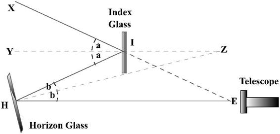
In
the above I is the index glass and H is the Horizon glass.
A ray of light ‘XI’ is first incident on the index
glass I and then is reflected onto the horizon glass H.
The horizon glass, H, reflects this light onto the
eyepiece of the telescope, E.
IY and HZ are the two the normals’
to the Index glass and the Horizon glass respectively; that is the direction
perpendicular to the planes of the mirrors.
The normals’ when extended
meet at Z so that / YZH is the
same as the angle which measures the inclination of the planes of the
mirrors.
XIE is the original ray produced to meet the second
reflected ray at E.
It is required to prove that the angle at E is equal
to twice the angle at Z, i.e., E=2Z.
The proof depends upon two geometry theorems: -
If two straight lines intersect one another, then the
vertically opposite angles are equal.
If a side of a triangle were produced then the
exterior angle shall be equal to the sum of the two interior opposite angles.
/ XIY = / YIH, because the angle of incidence is
equal to the angle of reflection, and / IHZ= / EHZ, for
the same reason.
Let these equal angles be denoted by a and b respectively.
In triangle HZI, the exterior angle
YIH Z +
IHZ
i.e. a Z + b
or 2a 2Z + 2b
In triangle HIE the exterior angle
XIH = 2a = E + 2b
2Z
+ 2b = E + 2b
i.e. 2Z= E
A division on the arc of a sextant is of One degree.
The value of a division on the micrometer is One
minute.
To what accuracy can you obtain a reading on a modern
sextant?
Since the micrometer is divided into 5/10 equal parts,
it depends. We can get a reading of 0.1 – 0.9 minutes of a degree.
Pierre Vernier, a Frenchman, about the year 1681,
developed vernier or a small arc, which gives in greater detail the measurement
of a large scale.
Describe the principle of the vernier/ micrometer?
A vernier/micrometer is constructed on the principle
that the length of a vernier/micrometer is made, equal to a certain number of
divisions of a fixed scale and is then divided into one more or one less than
that number of equal divisions. Thus 1 degree of the fixed scale may be divided
into 5 or 10 parts on the vernier/ micrometer.
What is the error of perpendicularity?
It is an error, which would be caused if the index
glass were not perpendicular to the plane of the instrument.
How
could that error (if any) be corrected?
By making what is called the "First
adjustment" of the sextant.
How do you make the "First adjustment”?
Look through the Index glass at the real and the
reflected arc, if both are not in the same straight line then adjustment is
required. Spring clip 1st. adjustment screw.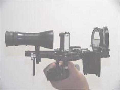


Place the index arm about the middle of the arc, and hold the
sextant face up and arc away from you and look slantingly into the index glass
so that you can see the real arc (just clear of the index glass) and the
reflected part of the arc in the index glass.
If they appear as one continuous arc the index glass
is perpendicular to the plane of the sextant.
If not, the adjustment is made by gently turning the screw at the back
of the index glass until they do.
What is side error?
An error, which would be
caused by the horizon glass not being perpendicular the plane of the
instrument.
Could side error (if any) be corrected?
Yes, by making what is called the "Second
adjustment" of the sextant.
How
do you make the "Second adjustment"?
Clamp the index at zero, hold the instrument
horizontally and look through the telescope and horizon glass at the
horizon. If the true and reflected
horizons appear in one straight line there is no side error. If they do, not, side error exists, but can
be removed by gently turning the top screw at the back of the horizon glass
(the screw farthest from the plane of the instrument).
2nd adjustment screw.
How
could you make the second adjustment at night when a distinct horizon is not
visible?
By means of a star. Clamp the index at zero, hold the sextant
vertically and look through the telescope and horizon glass at the star. Should the star and its reflection appear in
exact coincidence then there is no side error.
If one appears at the side of the other, side error exists. It may be
removed by gently turning the top screw at the back of the horizon glass until
they are in exact coincidence.
What is the "Third adjustment"?
To set the horizon glass parallel to the index glass
when the index is clamped at zero.
How
would you make the third adjustment?
Clamp, the index at zero,
hold the sextant vertically and look through the telescope and
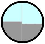
horizon glass at the horizon. Should the
true and reflected horizons appear in one continuous line, the horizon glass is
parallel to the index glass.
If the true horizon appears above or below the
reflected one, then the horizon glass is not parallel to the Index glass.
It
has to be adjusted by turning the screw at the back of the horizon glass (the
screw which is close to the frame of the sextant), until the two horizons
appear in the same straight line.
Could you make this adjustment at night?
Yes, by means of a star. Clamp the index at zero, hold the sextant
vertically and look through the telescope and horizon glass at the star. If the star and its reflection exactly
coincide, the horizon glass is parallel to the index glass, if one appears
above the other it is not parallel.
That being the case, the adjustment can be made by
gently turning the screw at the back of the horizon glass.
Would the making of one adjustment upset the other?
Yes because the one reacts slightly on the other. The second and third adjustments are usually
made at the same time, by gently turning one screw and then the other until
both adjustments are perfect.
What would you do if your sextant were not fitted with
a screw for making the third adjustment?
Find the index error and apply it to all
readings.
How could you find the index error?
By the horizon or a star, or
by the sun.
Describe the method of finding the index error by the
horizon.
Clamp
the index at zero, hold the sextant vertically, and look through the telescope
and horizon glass at the horizon. If the
true and reflected horizons appear in one straight line there is no index
error. If not, move the tangent screw
until they do.
The reading will be the index error, which must be added
if off the arc, but subtracted if on the arc.
How would you find the index error by a star?
Clamp the index at zero, hold the sextant vertically,
and look through the telescope and horizon glass at the star. Should the true and reflected stars coincide
there is no index error. If two stars
are visible (true and reflected), turn the tangent screw until they
coincide-that is, appear as one. The
reading will be the index: error to be added if it is off the arc, but
subtracted if on.
How would you find the index error by the sun?
Clamp the index about 32' off the arc. Hold the sextant vertically, and look, through the telescope and horizon glass at the sun.
Two suns will appear one above the other, one being
the true image and the other the
reflected
one.
Tangent screw![]()
Turn the tangent screw until the limbs of the two suns are in
exact contact, and note the reading.
Then
clamp the index about 32' on the arc, bring the limbs of the true and reflected
suns again in contact, and note the reading.
Subtract the lesser reading from the greater and
divide the difference by two.
The result is the index error to be subtracted if the
greater reading is on the arc, but to be added if the greater reading is off
the arc.
If the altitude of the sun is very small, refraction will
affect the upper and the lower limbs to a different extent. To get away from
this we can bring the suns’ limbs sideways, by holding the sextant horizontally
and proceeding in the same manner as described.
How do you know if your result is a correct one?
By adding the two readings together (ON and OFF the
arc) and dividing the result by four, the semi -diameter of the sun is
obtained. If the days’ semi-diameter of the sun, from the Almanac is nearly the
same then the result is an accurate one.
Why do you
clamp the index at 32’ OFF and ON the arc?
Because the diameter of the
sun is approximately the same. Also the limbs of the virtual and
the real sun will appear very close to each other and a small turning of the
tangent screw will give us the Index Error.
Which do you consider to be the best method of finding
the index error?
The method by the sun
because the semi -diameter in the Nautical Almanac gives me a check on the
readings.
What is the index error and semi-diameter of the sun,
if we have the following readings?
31.2’ OFF the arc.
32.2’ ON the arc.
The IE will be the difference between the ON and the
OFF reading divided by two.
Therefore: 32.2’ – 31.2’ = 1.0/2 = 0.5’ ON the arc,
since the ON reading is more.
Therefore the IE of 0.5’ (On) will have to be
subtracted from the altitude.
For the semi-diameter the two readings are added and
then the result is divided by four. This should agree with the SD of the sun
published for that day in the Almanac:
32.2’ + 31.2’ = 63.4/4 = 15.85’ – this should agree
with that in the Nautical Almanac.
Do you expect the index error to vary In the course of
time, or is it likely to remain constant?
Changes of a varying amount are likely to take place.
The sextant should be checked for IE before all-important sightings.
Could you find the index error by using any level
line, which was close to you to represent horizon?
No, there would be an error caused by the sextant
parallax.
How do you account for that?
The index glass and the horizon glass not being in the same horizontal plane when the index error is being found, rays of light proceeding from an object into these glasses produce an angle. This is perceptible when the observer is close to the object, but diminishes as the distance from the object increases. In a moderate sized sextant, the error at a distance of 5 miles would not exceed 1 second of the arc.
What is the error of collimation?
An error caused collimation or axis of the telescope
not being parallel to the instrument.
Describe how you would find out if there were an error of collimation, and how it may be corrected?
Screw the inverting telescope into the collar, focus
the eye piece, and turn it round until two of the wires in it are parallel to
the plane of the instrument. Select two Heavenly bodies separated by an angular
distance of not less than 90º, and bring them into exact contact with each
other and resting on the wire nearest to the plane of the instrument.
Now, tilt the sextant upwards so as to bring them on to the wire which is farthest away from the
plane of the instrument. They should
still appear in contact. If they do not,
there is an error of collimation.
If the objects appear to separate, the object end of
the telescope is inclined towards the plane of the instrument, and easing the
top screw in the collar and tightening the lower one makes the correction.
If the objects appear to overlap, the object end of
the telescope is included a from the plane of the
instrument, in which case the lower screw must be eased and the top one
tightened. It is essential that one screw should be eased before the other one
is tightened
What is graduation error?
Faulty graduation of the arc
or vernier or both of them.
When the index of the vernier is not coinciding with a mark on the arc,
only one of all the vernier divisions should then coincide with an arc
division. If more than one coincides
there is graduation error. Various parts
of the arc should be tested for it.
What is vernier error?
An error caused by the vernier being too high or too low on the arc. When the zero of the vernier is in coincidence with a division on the arc, the ten-minute mark on the vernier should also be in coincidence with a division on the arc. If it is not, there is vernier error. An optician must correct it.
What is shade error?
An error caused by the two faces of the shades not
being ground truly parallel to each other.
If it existed it would be of a different value for different shades or
combinations of shades. It could be
avoided by putting the dark eyepiece on to the telescope and using that in
preference to the shades.
What is centring error?
An error caused by the centre around which the index
bar revolves not being exactly the same as the centre from which the arc is
marked. It is purely a mechanical error
and cannot be removed.
By what method is it found?
By taking observations of stars of equal altitude
North and South of the zenith and finding the Latitude from them. The latitudes
obtained should be the same. If they are not, half the difference between the
two latitudes is the error for that altitude only.
As refraction may be unequal through differences of
temperature, and as there is the possibility of personal error, it is a matter
of great difficulty to find the centring error with
any degree of accuracy.
If the sun were exactly on your zenith, would the
altitude measured with a sextant be exactly 90º?
NO. If the sun were to be exactly on the zenith, the
altitude of its centre would be 90º.
There is no refraction or parallax at that altitude, but as the limb and not the centre has to be
observed, semi-diameter would have to be applied.
The Correction for "dip" would also be
necessary. The observed altitude would,
therefore, not be 90º.
By what method would you observe the altitude of the
sun if it was over the land, or if for any other reason the horizon under it
was not visible'?
If the altitude was not too low I would observe it by
taking what is known as a
“back angle " or " back observation."
How is this done?
By assuming an attitude as comfortable as possible, it
being necessary to bend the head backwards, and bringing the reflected image of
the sun to the horizon farthest from it.
How are angles corrected when obtained by a back
observation?
Corrections for index error (if any), dip, and
semi-diameter are applied in the usual manner, but those for refraction and
parallax in the opposite way.
The corrected angle must he taken from 180º to get the true altitude.
What would the sun’s true altitude be if obtained from
the following back observation:
Observed sextant angle – 118º20’ (lower limb), IE – 2’
OFF, sun’s SD for the day – 16.0’, height of eye – 22feet
61º25.9’
Establish Position By
Terrestrial Observations
Practice Horizontal Sextant Angles:
A horizontal angle is the angle at the observer
between two known horizontally separated shore objects. Horizontal sextant angles are used to fix
ships position, and for doing so require at least 3 objects. Horizontal angles may also be obtained by
taking compass bearings of the three objects.
Use of Horizontal Sextant Angles:
Danger Circle – assists in safe navigation by keeping
a constant clear distance from an obstruction.
To obtain vessel’s position.
To obtain blind and shadow
sector of the radar.
How is Sextant used to obtain Horizontal angles?
Hold the sextant horizontally with the Index bar set
at zero and look at the first object through the telescope. Slowly using the Index bar “on the arc”,
superimpose the reflection of the first object on the second object – finer
adjustments can be made with the help of the micrometer. The reading on the sextant gives the
horizontal sextant angle between the two objects. Similarly take the horizontal sextant angle
between the second and third object.
These two readings are used to fix the vessel.
The difference in the compass bearings of two objects
taken from the same repeater will also give the horizontal angle between the
objects. Two such readings can also be
used to determine the ships position.
METHOD OF OBTAINING THE SHIPS POSITION
The theorem that the angle subtended at the centre of
the circle is twice the angle subtended at the circumference is applied.
Consider the above diagram
– If q is the
horizontal angle between the two objects as obtained at O then:
Draw a line joining both the objects A and B.
Lay an angle 90º-q at A and B to intersect at C
With C as centre and AC or BC as radius draw a circle
passing through the objects A and B.
This
will give the position circle on which the vessel lies.
Similarly with Objects B and C obtain another position circle and the intersection of these two circles will give the position of the ship.
A STATION POINTER IS AN INSTRUMENT THAT FACILITATES
THE QUICK PLOTTING OF HORIZONTAL ANGLES.
Choosing Objects for Horizontal angle fixes:
Objects should be chosen so that at least one of the
following conditions applies:
Objects are either all on or near the same straight
line, and the centre object is nearest the observer.
The centre object is nearer the ship than the line
joining the other two.
The ship is inside the triangle formed by the objects
or on the outer edge.
At least one of the angles observed changes rapidly as
the ship alters position.
The sum of the two angles should be more than
50º. Better results will be obtained if
neither angle is less than 30º.
Horizontal Danger Angle:
The horizontal angle between two
objects can be used to navigate in such a way so as to keep a clear distance
from a particular obstruction or danger.
Since the observation gives a circle of position – for a ship lying on
that circle, the horizontal sextant angle between the two same objects will be
the same anywhere on the circle as shown in figure below. Hence keeping a constant horizontal sextant
angle between the two objects one can sail around a danger on a track known as
the